Electromechanical coupling hybrid modeling method for electric drive system

An electric drive system, electromechanical coupling technology, applied in the direction of electrical digital data processing, computer-aided design, special data processing applications, etc., can solve the problems of insufficient electrical performance, affecting equipment development, and high cost

Active Publication Date: 2019-08-02
CHONGQING UNIV OF TECH +1
View PDF9 Cites 3 Cited by
  • Summary
  • Abstract
  • Description
  • Claims
  • Application Information

AI Technical Summary

Problems solved by technology

This brings two problems: one is that the design and manufacturing precision proposed by electrical designers is too high, which often exceeds the ability of mechanical structure design and manufacturing; second, sometimes the mechanical structure accuracy requirements are met, but the electrical performance is not satisfied, resulting Servo drive equipment has a long development cycle, high cost, and heavy structure, which seriously restricts the improvement of its overall performance and affects the development of next-generation equipment
[0005] The traditional electromechanical coupling modeling and control research and electromechanical separation design based on empirical "assumptions" have seriously affected the development of my country's industrial and national defense major equipment and engineering, and have become a long-term constraint on the performance of servo drive equipment and affect the development of next-generation equipment. Bottleneck problem

Method used


Image

  • Electromechanical coupling hybrid modeling method for electric drive system
  • Electromechanical coupling hybrid modeling method for electric drive system
  • Electromechanical coupling hybrid modeling method for electric drive system

Examples


Embodiment

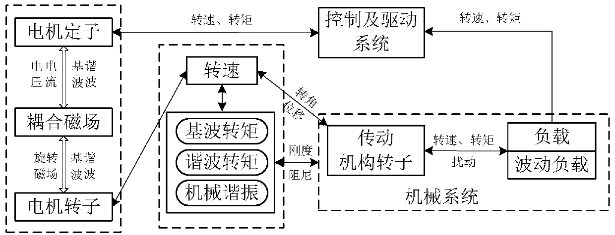
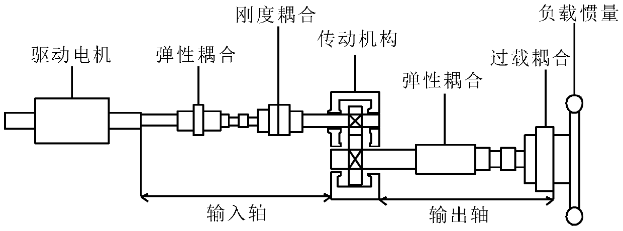
[0031] Example: see figure 2 , an electromechanical coupling hybrid modeling method for an electric drive system, comprising the following steps:

[0032] 1) Establish a mechanical dynamics model based on viscoelastic macroelements

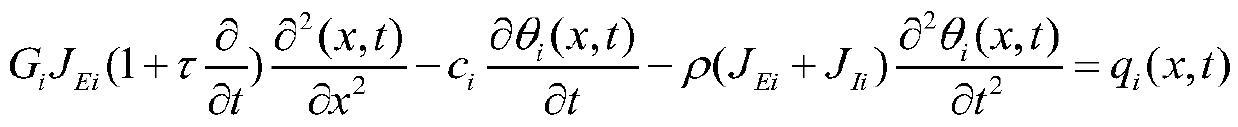
[0033] Establish a one-dimensional hybrid dynamics model composed of viscoelastic macroelements and discrete oscillators, use continuous viscoelastic macroelements to model the flexible rotor shafting, and use discrete oscillators to represent the rotor bearing support and inertia elastically attached to the shaft; use geometry The section polar moment of inertia is used to characterize the torsional stiffness and inertia properties of the viscoelastic macroelements in the hybrid model. The torsional motion of each geometric section viscoelastic macroelement is:

[0034]

[0035] Where: θ i (x,t) is the angular displacement of the rotation axis, τ is the lag time in the material damping Voigt model, G i Indicates the Kirchhoff (shear) modul...


PUM


Abstract

The invention discloses an electromechanical coupling hybrid modeling method for an electric drive system. The method comprises the following steps: 1) establishing a mechanical dynamics model based on a viscoelastic macro-unit, establishing a one-dimensional hybrid dynamics model composed of the viscoelastic macro-unit and discrete vibrators, modeling a flexible rotor shaft system by adopting thecontinuous viscoelastic macro-unit, and characterizing support and inertia of a rotor bearing elastically attached to the shaft by utilizing the discrete vibrators; 2) establishing Park electric model of an electric drive system under alpha-beta dq rotation orthogonal coordinates; assuming that magnetomotive force generated by the asynchronous motor is distributed along an air gap according to asine rule, and obtaining voltage and current in a three-phase asynchronous motor winding; and 3) establishing electromechanical coupling deep hybrid modeling of the electric drive system based on theharmonic balance method. The method solves the problem of deep fusion modeling among multiple physical quantities of rotation speed, current, flux linkage and load, and can provide a more accurate model for electromechanical coupling control of the electric drive system.

Description

technical field [0001] The invention relates to the technical field of electromechanical coupling modeling, in particular to an electromechanical coupling hybrid modeling method for an electric drive system. Background technique [0002] In recent years, electric drive systems have been widely used in many industrial fields such as CNC machine tools, robots, precision machinery, ship propulsion systems, electric vehicle drive systems, high-end test equipment, and defense industries. With the development of ultra-precision, high dynamics and integration, this puts forward higher requirements for the design and control of electric drive systems. [0003] Electric drive system is a typical complex electromechanical system including drive motor, transmission mechanism and control system. It can be divided into three parts: mechanical system, electrical system and coupling magnetic field connecting them (such as figure 1 shown). The mechanical coupling parameters of the electro...

Claims


Application Information

Patent Timeline
Patent Type & Authority Applications(China)
IPC IPC(8): G06F17/50
CPCG06F30/17G06F2119/06G06F30/20
Inventor 李文礼邵雅雯张友松赵瑞李建波刘永康陈远航
Owner CHONGQING UNIV OF TECH
Why Eureka
Try Eureka