Adjustable clamp holder

A clamper, adjustable technology, applied in the direction of large fixed members, metal processing machinery parts, metal processing equipment, etc., can solve the problem that the clamping area and contact area between the clamper and the slide rail cannot be adjusted, and increase the length , Good fixing performance and large clamping force

Active Publication Date: 2019-08-06
CHONGQING HONGGANG CNC MACHINE TOOL
View PDF9 Cites 0 Cited by
  • Summary
  • Abstract
  • Description
  • Claims
  • Application Information

AI Technical Summary

Problems solved by technology

[0004] The present invention intends to provide an adjustable clamper to solve the problem that the clamper in the prior art cannot adjust the clamping area and contact area between the clamper and the slide rail

Method used


Image

  • Adjustable clamp holder
  • Adjustable clamp holder
  • Adjustable clamp holder

Examples


Embodiment

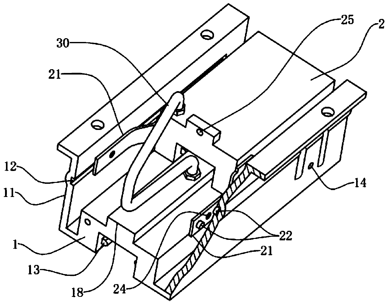
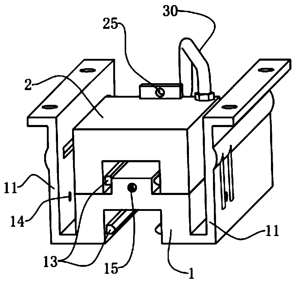
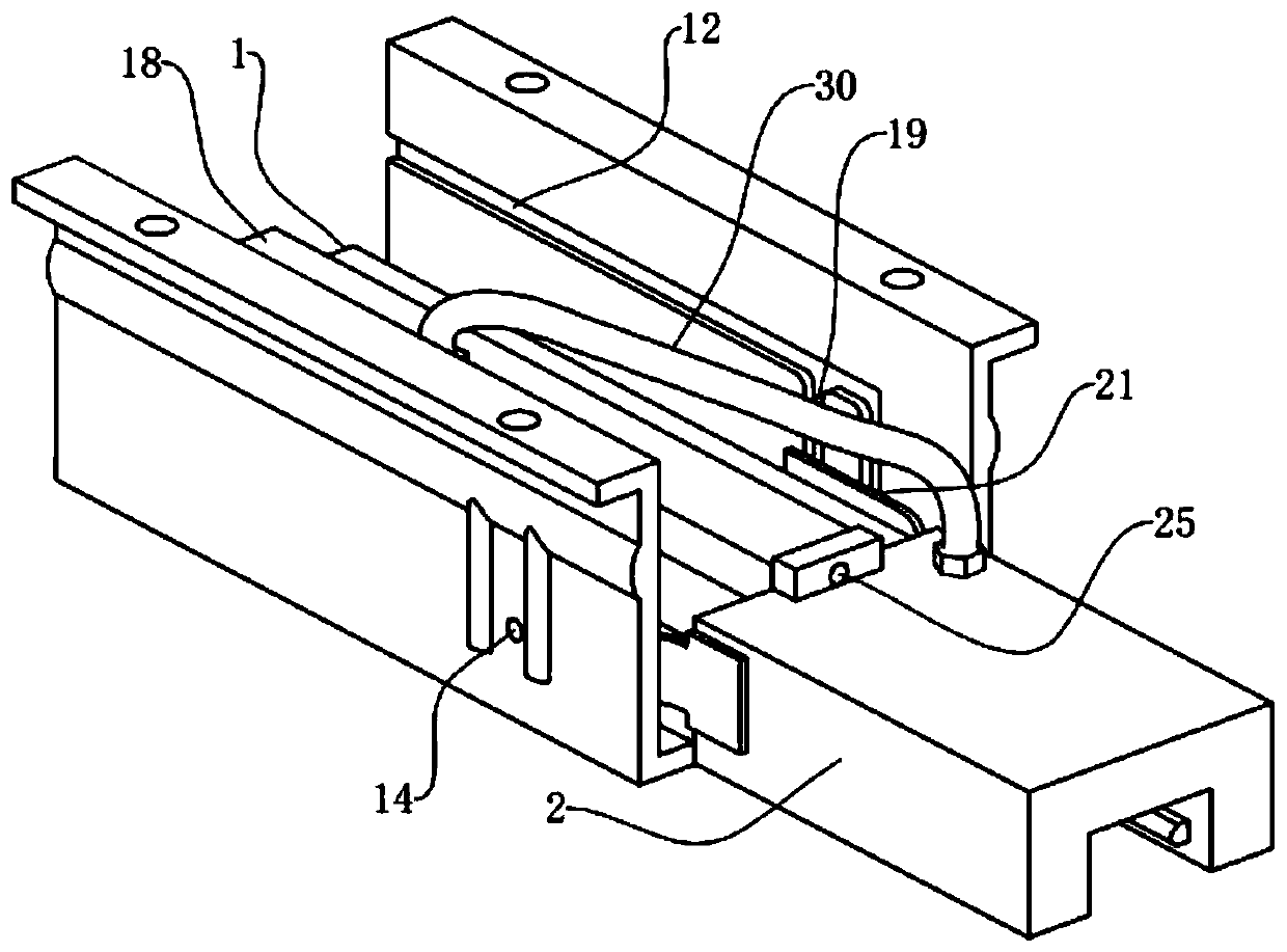
[0030] The embodiment is basically as follows:

[0031] An adjustable gripper such as figure 1 As shown, it includes the main gripper 1 and the auxiliary gripper 2 with the same structure. The length of the auxiliary gripper 2 is about 1 / 2 of the length of the main gripper 1. Both sides of the main gripper 1 are fixedly connected with installation Plate 11, there is a gap between the mounting plate 11 and the side of the main holder 1, and the mounting plate 11 and the shell of the main holder 1 are integrally formed. The lower parts of the main gripper 1 and the auxiliary gripper 2 are provided with gripping grooves, and hydraulic oil chambers are arranged inside. The two hydraulic oil chambers are connected through a flexible hydraulic oil pipe 30. The hydraulic oil chamber of the main gripper 1 is connected to a hydraulic system. The side walls of the clamping groove are provided with clamping blocks 13, and the clamping blocks 13 are controlled by the hydraulic oil pipes ...


PUM


Abstract

The invention relates to the technical field of machine tool part equipment, in particular to an adjustable clamp holder. The clamp holder comprises a main clamping device and an auxiliary clamping device, wherein the main clamping device is provided with a containing part capable of accommodating the auxiliary clamping device. The main clamping device is in sliding connection with the auxiliary clamping device, the specific sliding connection mode is that a transverse sliding groove is formed in the inner wall of the containing part, and the auxiliary clamping device is fixedly provided withan extending plate, wherein the extending plate is fixedly provided with vertical sliding grooves matched with the transverse sliding groove. The main clamping device is connected with a hydraulic system, and the auxiliary clamping device communicates with the main clamping device through a hydraulic oil pipe. According to the adjustable clamp holder, the auxiliary clamping device can be installedon the main clamping device, and therefore the clamping area and the contact area of the clamping holder can be adjusted, thus making the clamp holder suitable for machining different work pieces.

Description

technical field [0001] The invention relates to the technical field of machine tool parts and equipment, in particular to an adjustable clamper. Background technique [0002] In the process of workpiece processing, it often involves that the bed saddle needs to move from the starting position to the end position within a fixed stroke; the existing technology generally sets the slider at the bottom of the bed saddle, and the slider cooperates with the slide rail on the bed , so that the slider can slide freely on the slide rail; in order to facilitate the saddle to stop when it slides to the corresponding position of the slide rail, a clamper is installed at the bottom of the saddle, and the external shape of the clamper is similar to that of the slider , can also slide along the slide rail without clamping. [0003] For different workpieces and workpiece materials, some workpieces need better position fixing performance when the saddle is working, that is, the clamper needs...

Claims


Application Information

Patent Timeline
Patent Type & Authority Applications(China)
IPC IPC(8): B23Q1/01B23Q1/26B23Q5/34
CPCB23Q1/017B23Q1/26B23Q5/34
Inventor 汪传宏
Owner CHONGQING HONGGANG CNC MACHINE TOOL
Why Eureka
Try Eureka