
Turning flutter acceleration collection system and method based on machine vision

A machine vision and acquisition method technology, applied in metal processing equipment, metal processing mechanical parts, measuring/indicating equipment and other directions, can solve the problems of inaccurate acceleration signals, complex turning chatter inducements, and chatter effects, etc., to ensure accurate sexual effect

Active Publication Date: 2019-08-06
CHANGSHA UNIVERSITY OF SCIENCE AND TECHNOLOGY
View PDF7 Cites 7 Cited by
  • Summary
  • Abstract
  • Description
  • Claims
  • Application Information

AI Technical Summary

Problems solved by technology

At present, the acquisition method of chatter acceleration signals is mainly to install piezoelectric acceleration sensors on the machine tool. Turning chatter itself has complex causes. If contact sensors are used, it may affect the chatter vibration, resulting in inaccurate acceleration signals.

Method used


Image

  • Turning flutter acceleration collection system and method based on machine vision
  • Turning flutter acceleration collection system and method based on machine vision
  • Turning flutter acceleration collection system and method based on machine vision

Examples


Embodiment Construction

[0036] Such as figure 1 As shown, a machine vision-based turning chatter acceleration acquisition system includes:

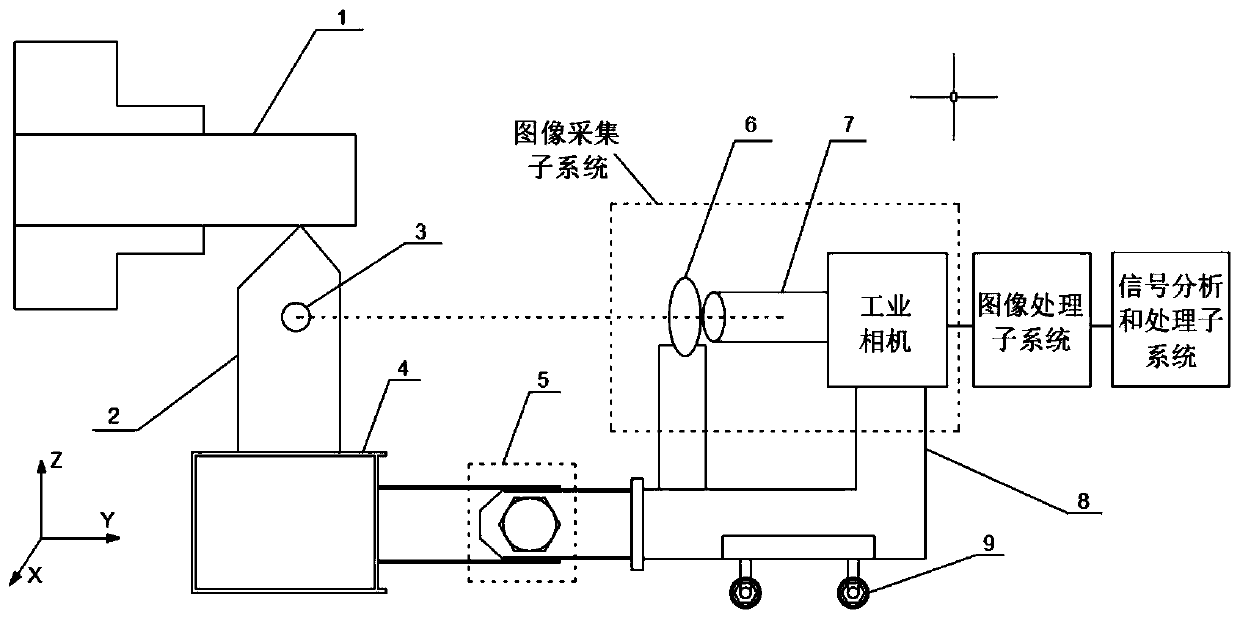
[0037] The image acquisition subsystem is set in the X direction shown in the figure; a circular marker 3 is set on the tool 2 as the characteristic area of ​​the collected image, and the marker should be set on the plane of the tool as much as possible, and its diameter should not exceed Knives are attached figure 1 indicated by the Y-direction width of the A magnifying glass 6 is set on the connection between the camera lens 7 and the marker 3, wherein the distance between the magnifying glass and the camera lens is 0 for obtaining enlarged and clear images; flexible connection, in the attached figure 1 The Y direction shown is in a linked state, and the Z direction can move freely, so as to ensure that the camera lens 7, the magnifying glass 6 and the marker 3 are in the vicinity when the tool 2 moves axially. figure 1 The shown X direction is always on ...


PUM


Abstract

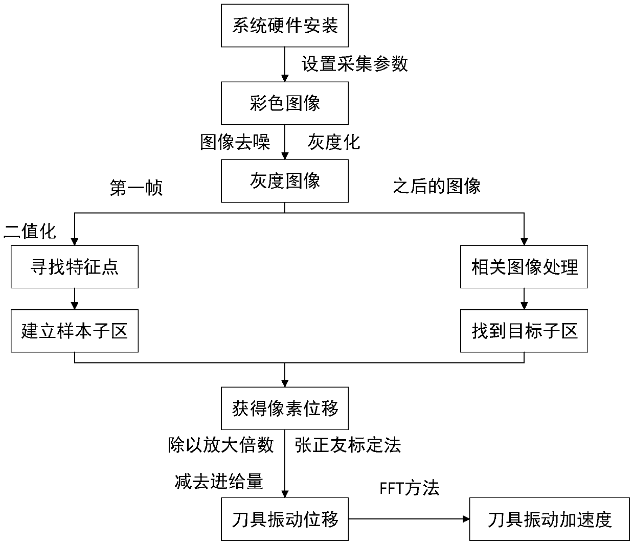
The invention discloses a turning flutter acceleration collection system and method based on machine vision, and relates to the technical field of machine vision detection. The collection system and method are suitable for workpiece rotation, a tool does the axial turning machining, the system comprises an image collection subsystem, an image processing subsystem and a signal analysis and processing subsystem, and the method comprises the steps of firstly mounting all parts of the system, setting collection parameters to obtain an image, carrying out image pre-treating on a first frame image obtained by an industrial camera, seeking a characteristic area, building a sample sub area, carrying out same pretreatment on all frames of image, finding out a target sub area to obtain pixel displacement, according to the amplifying rate of an amplifying lens and the calibration method principle, obtaining the actual vibration displacement of the tool, and finally, adopting an FFT method to convert flutter displacement into flutter acceleration. The machine vision method is adopted, and the advantages of being free of contact and damage, high in precision and the like are achieved.

Description

technical field [0001] The invention relates to the technical field of fault detection of photoelectric technology, in particular to the field of vibration signal acquisition of turning chatter of machine vision technology. Background technique [0002] Turning chatter is an unstable phenomenon caused by factors such as the discontinuous cutting cycle between the tool and the cutting surface of the workpiece, and the proximity of the workpiece to a certain natural frequency of the turning system and machine tool. It is a vibration that does not attenuate. The occurrence of chatter during turning has many adverse effects on normal machining, such as low machining accuracy, lower product quality and production efficiency, and greater noise. In severe cases, it may even damage tools and machine tools, posing a threat to personal safety. Therefore, online monitoring of turning chatter is very necessary, and the importance of accurately obtaining chatter signals in turning chatte...

Claims


Application Information

Patent Timeline
Patent Type & Authority Applications(China)
IPC IPC(8): B23Q17/12B23Q17/24
CPCB23Q17/12B23Q17/2409
Inventor 王向红谭小辉胡宏伟易可夫
Owner CHANGSHA UNIVERSITY OF SCIENCE AND TECHNOLOGY
Learn More