Multifunctional automatic metallographical experimental part grinding and polishing device and environment-friendly grinding method
A polishing device and experiment technology, applied in the direction of grinding/polishing safety device, grinding device, grinding/polishing equipment, etc., can solve the problem that the grinding quality of the phase test piece cannot be guaranteed to be uniform, the effect of metallographic structure observation is affected, and the scope of application is limited. and other problems, to achieve the effect of saving inlaid powder materials and processing time, ensuring strength, and improving utilization efficiency
- Summary
- Abstract
- Description
- Claims
- Application Information
AI Technical Summary
Problems solved by technology
Method used
Image
Examples
Embodiment 1
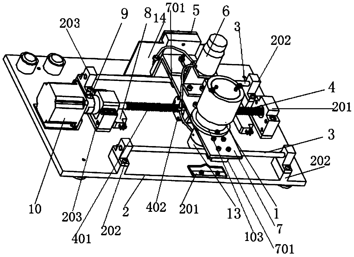
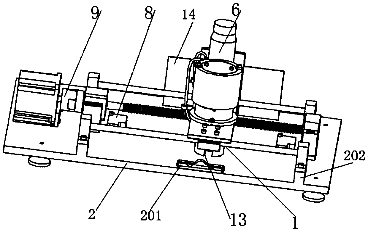
[0045] An automatic grinding and polishing device for metallographic test pieces, which is characterized by comprising a clamp A1, a bottom plate 2, a sliding rod 3, a screw 4, a clamp B5, a mounting plate 7 and a stepping motor 10.
[0046] The stepping motor 10, two bearing seats 203 and four vertical plates 202 are fixedly mounted on the upper surface of the bottom plate 2. The four vertical plates 202 support two parallel sliding rods 3. Between the two sliding rods 3 is a lead screw 4. Bearings supported by the bearing seat 203 are installed on both ends of the screw 4. After one end of the screw 4 passes through the inner ring of the bearing, it is connected to the rotating shaft of the stepping motor 10 through a coupling. Sandpaper is laid on the upper surface of the bottom plate 2.
[0047] The mounting plate 7 is supported above the bottom plate 2 by two sliding rods 3. The screw nut 402 of the screw 4 is fixedly connected to the lower surface of the mounting plate 7....
Embodiment 2
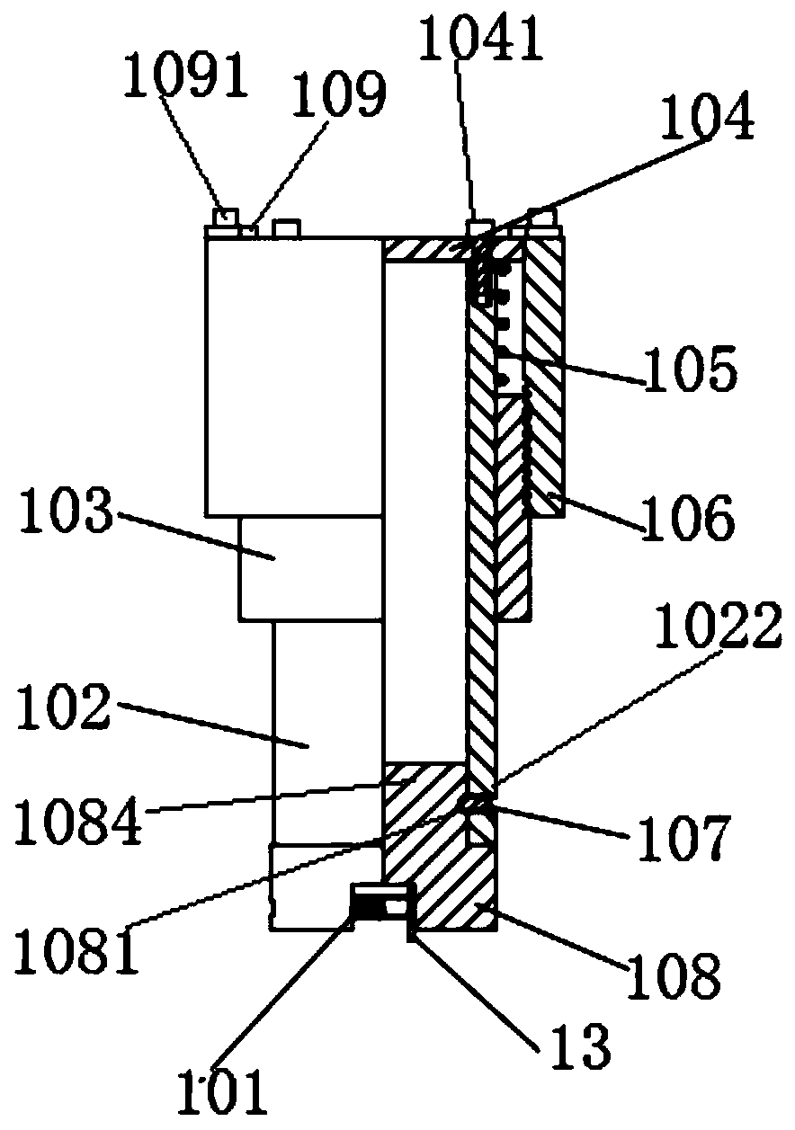
[0053] The main structure of this embodiment is the same as that of Embodiment 1. Furthermore, the upper cover 104 is connected to the upper end of the hollow optical shaft 102 by a screw 11041.
[0054] The upper end of the internally threaded shaft sleeve 106 is connected to two limiting blocks 109 by screws II1091. The limiting block 109 blocks above the upper cover 104.
[0055] The upper end of the movable chuck 108 is a boss 1084 embedded in the lower end of the hollow optical shaft 102. Four hemispherical grooves 1081 are evenly distributed on the side wall of the boss 1084. The side wall of the hollow optical shaft 102 has a threaded through hole 1022. A ball plunger 107 is inserted into the threaded through hole 1022. One end of the ball plunger 107 enters the hemispherical groove 1081, thereby connecting the movable chuck 108 and the hollow optical shaft 102 together.
[0056] The outer side wall of the hollow optical axis 102 has a strip guide groove 1021 perpendicular...
Embodiment 3
[0062] This embodiment discloses an environmentally friendly grinding method for metallographic test pieces based on the device described in embodiment 2, characterized in that:
[0063] 1) Prepare metallographic test piece A13 and / or metallographic test piece B14
[0064] The metallographic test piece A13 is a thin sample or a square sample.
[0065] The metallographic test piece B14 is a sheet-shaped sample.
[0066] 2) First, fix 300# sandpaper on the upper surface of the base 2, and ensure that the sandpaper is flat and free of wrinkles.
[0067] 3) Install metallographic test pieces.
[0068] Place the metallographic test piece A, change its expansion and contraction by rotating the clamping screw 101 to realize the clamping process, and rotate the outer threaded shaft sleeve to make the metallographic test piece A closely fit the sandpaper.
[0069] The metallographic test piece B is placed, the amount of expansion and contraction is changed by rotating the clamping screw 502 to rea...
PUM
 Abstract
Description
Claims
Application Information
 - R&D
- Intellectual Property
- Life Sciences
- Materials
- Tech Scout
- Unparalleled Data Quality
- Higher Quality Content
- 60% Fewer Hallucinations
Browse by: Latest US Patents, China's latest patents, Technical Efficacy Thesaurus, Application Domain, Technology Topic, Popular Technical Reports.
© 2025 PatSnap. All rights reserved.Legal|Privacy policy|Modern Slavery Act Transparency Statement|Sitemap|About US| Contact US: help@patsnap.com


