

Cloth cutting device
A cutting device and fabric technology, which is applied in the cutting of textile materials, the device for coating liquid on the surface, and the trimming of the fabric surface, etc., can solve the problems of fluff polluting the environment and raw yarn, etc., to ensure quality and reduce manual labor The effect of intensity
- Summary
- Abstract
- Description
- Claims
- Application Information
AI Technical Summary
Problems solved by technology
Method used
Image

Examples
Embodiment 1
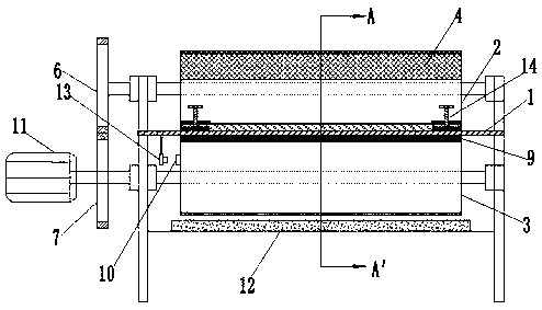
[0027] Such as Figure 1-2 As shown, a cloth cutting device includes a workbench 1, a first cylinder 2 is arranged above the workbench 1, a second cylinder 3 is arranged below the workbench 1, the length of the first cylinder 2 and the length of the second cylinder 3 are equal in length, and the diameter of the first cylinder 2 is equal to the diameter of the second cylinder 3; a heating device 4 and a pad 5 are arranged above the first cylinder 2, and the length of the heating device 4 is the same as that of the first cylinder 2. The same length, the length of the pad 5 is the same as the length of the first cylinder 2, the height value of the heating device 4 is twice the height value of the cutter 9, the heating device 4 is connected with the first cylinder 2 by bolts, and the heating device 4 There is a heating wire inside, and the temperature of its surface can be controlled by controlling the magnitude of its current; the length of the pad 5 is equal to the length of the...
Embodiment 2
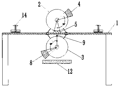
[0029] Such as image 3 As shown, when the cloth 15 needs to be cut, the cloth 15 is unfolded, the cutting size is measured, the cutting line is drawn, the cutting line is aligned with the center line of the width of the hollowed out area, and the two ends of the workbench 1 and the two sides of the clamping device 14 are used. The cloth 15 is clamped, the stepping motor 11 is started to rotate, the stepping motor 11 drives the first gear 6 to rotate, the first gear 6 drives the second cylinder 3 to rotate, and the first gear 6 drives the second gear 7 to rotate in the opposite direction at a constant speed. The second gear 7 drives the first cylinder 2 to rotate, and the brush 8 soaked with white latex above the second cylinder 3 is in contact with the cloth 15, and the white latex is immersed in the cutting line area of the cloth 15; The table is high, and the brush 8 lifts the cloth 15 upwards, and the force between the two can fully immerse the white latex in the cloth 1...
Embodiment 3
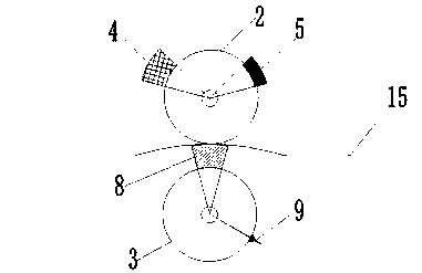
[0031] Such as Figure 4 As shown, along with the rotation of the second cylinder 3, the brush 8 leaves the cloth 15 cutting line position, and the heating device 4 on the first cylinder 2 moves to this place, and the white latex immersed in this place is heated and dried; The device 4 is lower than the workbench 1, and the heating device 4 presses down the cloth 15, and the contact between the two is closer, and since the height of the heating device 4 is equal to the height of the brush 8, the white latex immersed by the brush 8 can be removed. Full heating; by adjusting the rotation speed of the stepping motor 11 and then adjusting the contact time of the heating device 4 and the cloth 15, the heating temperature of the heating device 4 can also be adjusted to ensure that the white latex is completed within the contact time of the heating device 4 and the cloth 15 dry.
PUM
 Abstract
Description
Claims
Application Information