Acousto-optic rhythm control system and control method

An acousto-optic and vibrating cavity technology, which is applied in the acousto-optic rhythm control system and control field, can solve the problems of not being able to realize lighting effects efficiently and conveniently, and achieve the effect of convenient use

Active Publication Date: 2019-08-06
北京利合世旺教育科技有限公司
View PDF5 Cites 1 Cited by
  • Summary
  • Abstract
  • Description
  • Claims
  • Application Information

AI Technical Summary

Problems solved by technology

[0004] Therefore, no matter it is based on the speaker or the music and lighting rhythm technology based on the single-chip microcomputer and programming, it cannot efficiently and conveniently realize the lighting effect with strong expressive force.

Method used


Image

  • Acousto-optic rhythm control system and control method
  • Acousto-optic rhythm control system and control method

Examples


Embodiment 1

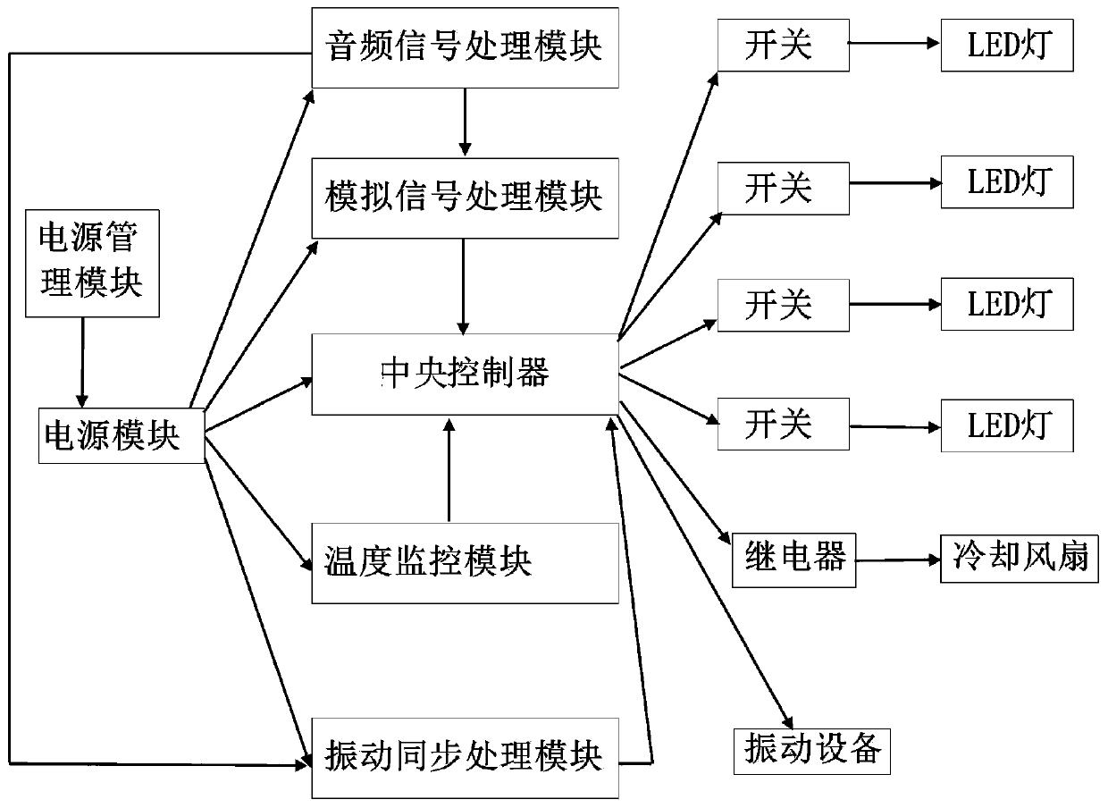
[0038] Such as figure 1 As shown, the embodiment of the present invention provides an acousto-optic rhythm control system, including: an audio signal processing module, an analog signal processing module, a temperature monitoring module and a vibration synchronization processing module;

[0039] The audio signal processing module is configured to perform frequency separation on the audio signal, obtain multiple audio signals of different frequencies, and send the multiple audio signals of different frequencies to the analog signal processing module;

[0040]The analog signal processing module is configured to perform analog processing on the voltage signals corresponding to the plurality of audio signals of different frequencies to obtain a control signal; wherein, the control signal is used to control the audio signal corresponding to each of the different frequencies Turn on or off the switch connected to the LED light of the corresponding color;

[0041] The temperature mo...

Embodiment 2

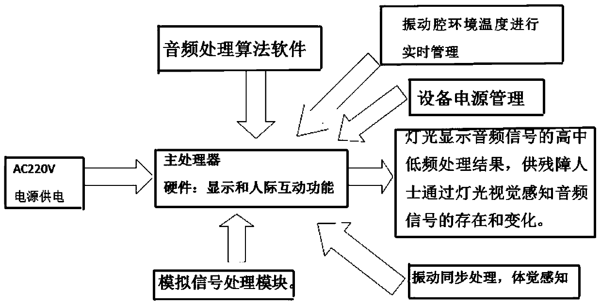
[0056] Such as figure 2 As shown, in the acousto-optic rhythm control system provided by Embodiment 2 of the present invention, a rhythm system first has the function of converting the audio signal changing in real time into a synchronous light signal for visual warning (through the PLC processor, the analog signal is processed The audio signal data sent by the module is compared with the preset data of the algorithm software program, and the comparison result is used to control the switch of the preset control terminal of the program. Through this switch, different LED lights are controlled, and the light emission and light color of the light correspond to the corresponding The audio signal to complete the visual warning), the adjustment of the display effect and real-time audio synchronization, the separation and adjustment of high frequency, intermediate frequency, low frequency, and full frequency (the audio signal sent by the audio playback device is effectively controlle...


PUM


Abstract

The invention provides an acousto-optic rhythm control system and control method, belonging to the technical field of acousto-optic rhythm conversion systems. An audio signal processing module of thedevice separates the frequencies of audio signals to obtain multiple audio signals of different frequencies. An analog signal processing module carries out analog processing on voltage signals corresponding to the multiple audio signals of different frequencies to obtain a control signal. A temperature monitoring module collects the working temperature of a vibration chamber in real time, and controls the on-off of a cooling fan in the vibration chamber according to the working temperature. A vibration synchronization processing module amplifies the audio signals, and acquires a vibration signal according to the amplified audio signals, wherein the vibration signal is used to control the on-off of vibration equipment. The display effect and the real-time audio can be synchronously adjusted, and a rhythm and frequency light centralized control function is achieved. The environmental temperature of the embedded layer can be monitored in real time, and it is ensured that the vibration layer is not damaged by the influence of local climate change.

Description

technical field [0001] The invention relates to the technical field of an acousto-optic rhythm conversion system, in particular to an acousto-optic rhythm control system and a control method. Background technique [0002] The lighting system is pre-programmed manually according to the type of music, so as to control different lights to flash and change with the rhythm of the music. This system requires programmers to have a very deep understanding of the songs to be edited. These programmers need to write a special script for some common songs or melodies, and burn the script to the ROM (read-only memory) of the rhythm system. After the system is started, the lighting system is driven according to the data in the read-only memory. [0003] In the light rhythm technology based on pre-programmed single-chip microcomputer, because of the need to manually pre-program the script of the music effect, there are limitations in the scope of application. Since human beings have a var...

Claims


Application Information

Patent Timeline
Patent Type & Authority Applications(China)
IPC IPC(8): H05B33/08G10H1/00G10H1/40G10L21/10H05B44/00
CPCG10H1/0008G10H1/40G10L21/10H05B45/00Y02B20/30Y02B20/40
Inventor 颜培利
Owner 北京利合世旺教育科技有限公司
Why Eureka
Try Eureka