Friction stir welding structure applied to robot and working method thereof

A technology of friction stir welding and robots, which is applied in welding equipment, manufacturing tools, non-electric welding equipment, etc., can solve problems such as welding defect damage to equipment, high requirements for tooling and fixtures, instability and offset, etc., to reduce post-weld processing requirements, Reduce the requirements of fixtures and improve the effect of weld forming

Pending Publication Date: 2019-08-09
SHANGHAI FANUC ROBOTICS
View PDF0 Cites 7 Cited by
  • Summary
  • Abstract
  • Description
  • Claims
  • Application Information

AI Technical Summary

Problems solved by technology

[0005] 1. The requirements for tooling and fixtures are high. One of the conditions for the implementation of friction stir welding is the rigid holding of the workpiece to be welded. The single-shaft shoulder stirring head cannot provide the holding force of the workpiece, so complex tooling auxiliary mechanisms are required to hold the workpiece.
[0006] 2. It is difficult to control the constant pressure. When the single-shaft shoulder friction stir welding is implemented, because the workpiece cannot achieve absolute consistency, real-time pressure feedback control is required to adjust the amount of pressure. If the feedback is not timely or the feedback is wrong, it will cause welding defects and damage equipment.
[0007] 3. The control sensitivity of the down pressure is high. When the single shoulder friction stir welding is implemented, the stirring pin and the shoulder rotate at the same time. Under the influence of constant pressure control, it is easily affected by the material, structure and state, resulting in unstable down pressure. formation of welding defects
[0008] 4. Offset is generated. Because the shoulder of the single-shoulder stirring head and the stirring needle rotate at the same time, it will cause instability and offset when pressing into the workpiece, and the welding track cannot move according to the real track, resulting in welding defects.
[0009] 5. The welding seam is poorly formed. The single-shaft shoulder friction stir welding process will produce flashes and uneven fish scales. Post-processing will increase the process
[0010] 6. The welding quality is average. During the welding process of single shoulder friction stir welding, the stirring needle and the shoulder are pressed into the workpiece to be welded, resulting in a larger nugget area, heat affected area, and heat engine affected area of ​​the weld, which reduces the mechanical properties of the base metal. many

Method used


Image

  • Friction stir welding structure applied to robot and working method thereof
  • Friction stir welding structure applied to robot and working method thereof
  • Friction stir welding structure applied to robot and working method thereof

Examples


Embodiment Construction

[0041] The present invention will be further described below in conjunction with the accompanying drawings and specific embodiments, but not as a limitation of the present invention.

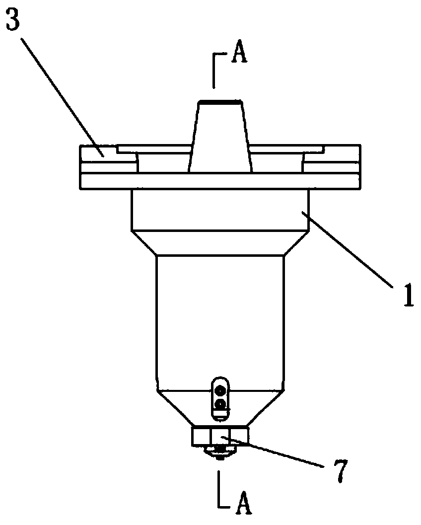
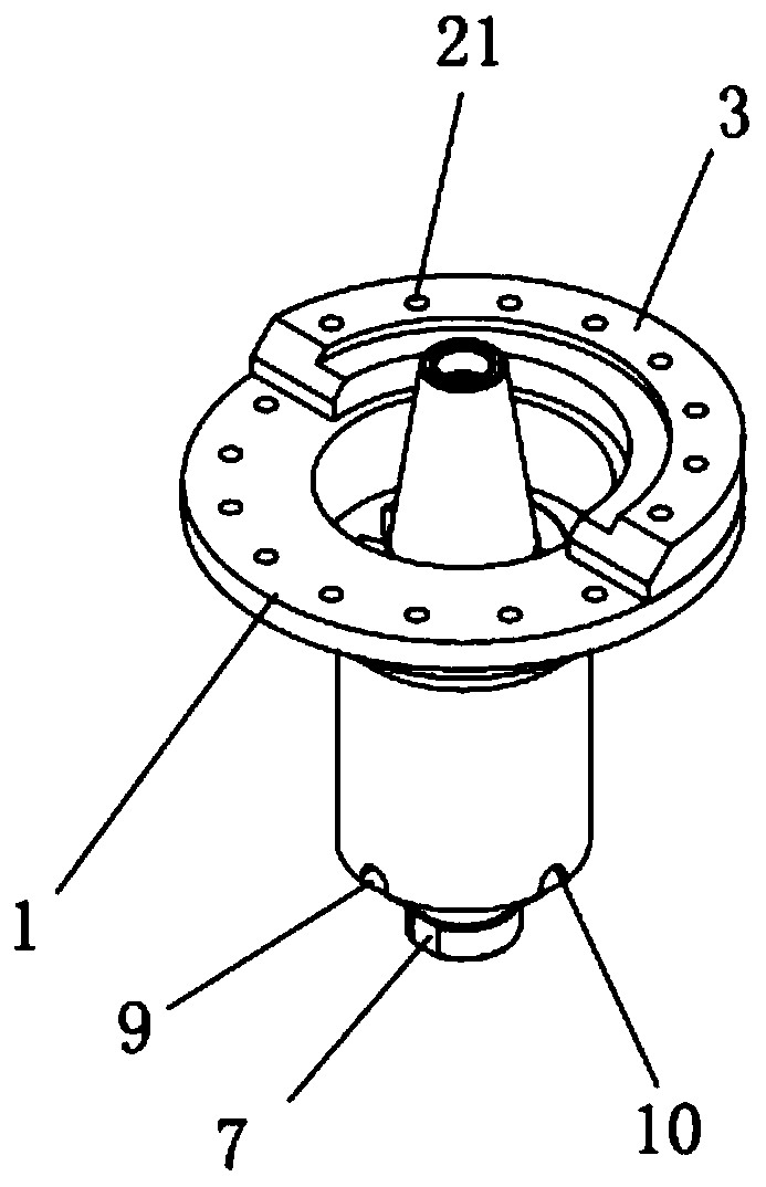
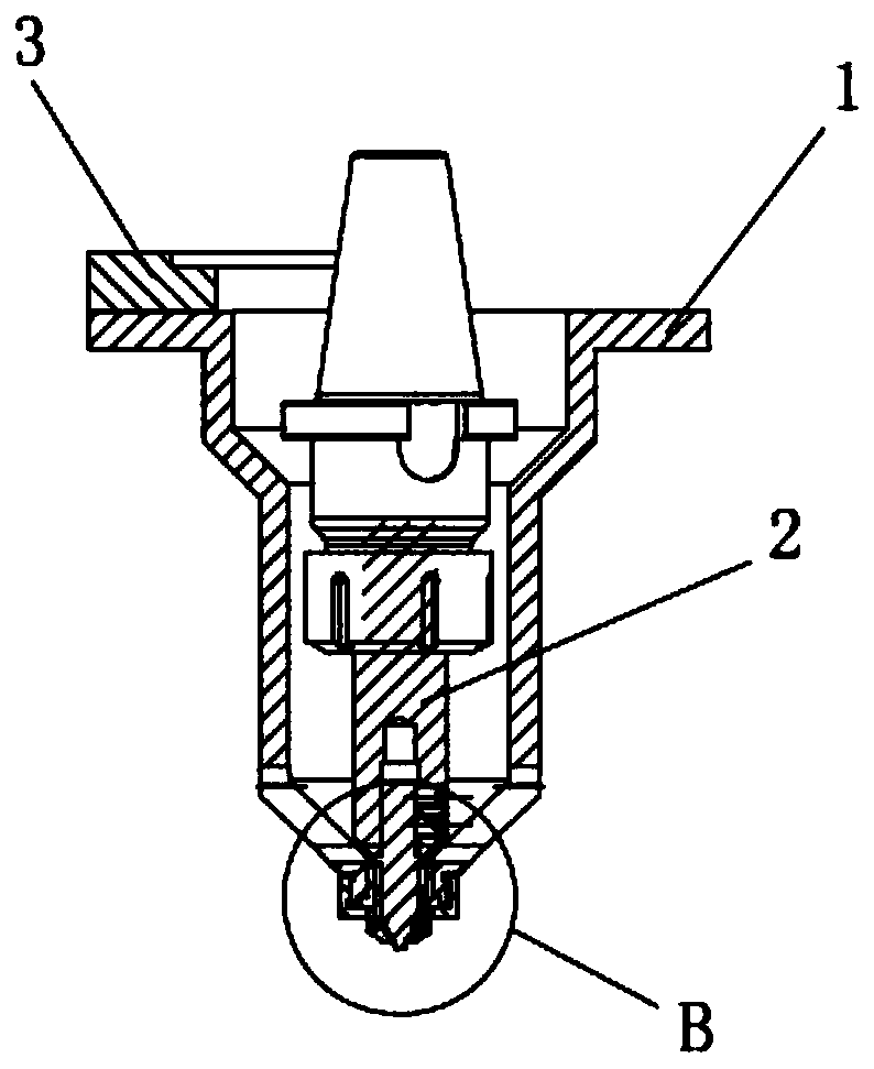
[0042] figure 1 is the front view of the friction stir welding structure applied to the robot in the present invention, figure 2 It is a perspective view of the friction stir welding structure applied to the robot in the present invention, image 3 yes figure 1 A-A sectional view in, Figure 4 yes image 3 Partial enlarged view of B in middle, Figure 5 It is a structural schematic diagram of a stirring needle in the present invention, Figure 6 It is a structural schematic diagram of the shaft shoulder in the present invention. See Figure 1 to Figure 6As shown, a preferred embodiment is shown, and a friction stir welding structure applied to a robot is shown, including: a friction stir welding structure applied to a robot, including a shaft shoulder sleeve 1, a shaft shoulder 4, Main ...


PUM


Abstract

The invention discloses a friction stir welding structure applied to a robot and a working method thereof, and relates to the technical field of friction stir welding equipment. The friction stir welding structure a shaft shoulder sleeve, a shaft shoulder, a main shaft connecting plate, a moving shaft connecting block, a stirring needle, an extension rod and a shaft shoulder locking nut, wherein the upper surface of the shaft shoulder sleeve is provided with the main shaft connecting plate, the shaft shoulder sleeve is connected with a robot friction stir welding main shaft through the main shaft connecting plate, the extension rod is arranged inside the shaft shoulder sleeve, a mounting hole is formed in the middle of the lower surface of the extension rod, the stirring needle is arrangedin the mounting hole, the lower end of the stirring needle protrudes downwards out of the shaft shoulder sleeve, a welding end is arranged at the lower end of the stirring needle, the shaft shoulderis arranged inside the lower end of the shaft shoulder sleeve, the lower end of the stirring needle penetrates through the shaft shoulder, a shaft shoulder pre-tightening hole position is formed in the lower end of the shaft shoulder sleeve, the shaft shoulder pre-tightening hole position is opposite to the shaft shoulder, and the locking nut is arranged in the shaft shoulder pre-tightening hole position. The friction stir welding structure has the characteristics of reducing the robot control difficulty, reducing the cost and improving the efficiency.

Description

technical field [0001] The invention relates to the technical field of friction stir welding equipment, in particular to a friction stir welding structure applied to a robot and a working method thereof. Background technique [0002] Friction Stir Welding technology is a solid-phase joining technology first proposed by the British Welding Institute (TWI) in 1991. This technology has gone from invention to large-scale industrial application in a short period of time. It is hailed as "another revolutionary welding technology after laser welding" by the industry. At present, this technology is widely used in aerospace, railway transportation equipment, shipbuilding, and automobile manufacturing, and it will be applied to more fields in the future. [0003] Robot friction stir welding has high flexibility, can realize complex trajectory movement, and makes welding of complex structural parts possible. Therefore, robot friction stir welding technology and equipment have become a...

Claims


Application Information

Patent Timeline
Patent Type & Authority Applications(China)
IPC IPC(8): B23K20/12B23K20/26
CPCB23K20/122B23K20/26
Inventor 杨坤孔萌张杰陈玉喜曾鹏
Owner SHANGHAI FANUC ROBOTICS
Why Eureka
Try Eureka