
Narrow gap laser welding protective method and narrow gap laser welding protective device

A laser welding and protection device technology, which is applied in the direction of laser welding equipment, welding equipment, metal processing equipment, etc., can solve the problems of irreparable, increased welding instability, welding, and dust accumulation, so as to avoid welding defects and facilitate application Promote and improve the effect of shielding

Active Publication Date: 2015-04-01
AVIC BEIJING AERONAUTICAL MFG TECH RES INST
View PDF5 Cites 7 Cited by
  • Summary
  • Abstract
  • Description
  • Claims
  • Application Information

AI Technical Summary

Problems solved by technology

In the thick plate laser narrow gap welding process, the protection methods widely used for the protection of the weld are coaxial air blowing and side blowing. However, due to the ultra-narrow weld seam, it is difficult for the shielding gas to reach the weld seam during the welding process. To form an effective purging effect at the root, a special method must be used to feed the gas, but this cannot move the welding fume away from the welding groove, which also makes it difficult to directly copy the general single-side blowing protection method to narrow-gap laser welding
[0004] 2. In the process of thick plate laser narrow gap welding, it is necessary to achieve single-layer multi-pass welding. The traditional side blowing or direct blowing can only make the welding fumes in the welding part shift at most, but most of them will fall back to the cooled one. Weld groove and weld seam, followed by welding can not sweep the fume, which will cause irreparable defects, so multiple welding may cause more fume to accumulate on the side wall of the weld groove
[0005] 3. In the laser deep penetration welding process, due to the periodic effect between the pinhole effect and the plasma, it will lead to periodic changes in the absorption of laser light during the welding process, and at the same time lead to changes in the laser absorbable power and weld width. as well as increased welding instabilities and welding defects
[0006] Therefore, based on the complexity of the narrow gap laser welding welding process, the applied basic research and related basic data on weld seam protection are far from enough to support the promotion of its application in actual industrial production.

Method used


Image

  • Narrow gap laser welding protective method and narrow gap laser welding protective device
  • Narrow gap laser welding protective method and narrow gap laser welding protective device
  • Narrow gap laser welding protective method and narrow gap laser welding protective device

Examples


Embodiment Construction

[0039] In order to make the object, technical solution and advantages of the present invention clearer, the present invention will be described in further detail below in conjunction with the embodiments and accompanying drawings. Here, the exemplary embodiments and descriptions of the present invention are used to explain the present invention, but not to limit the present invention.

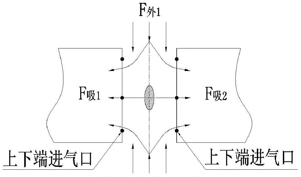
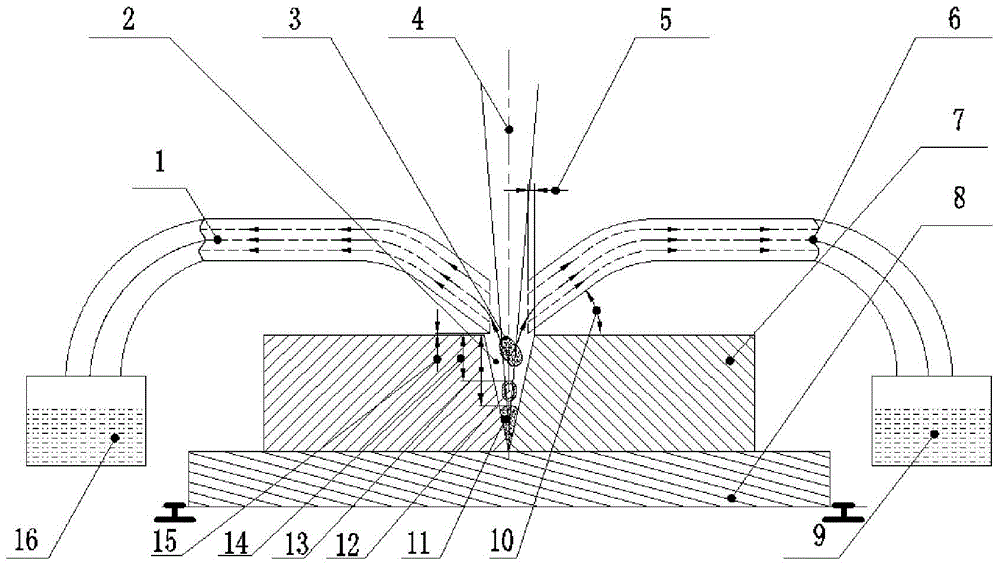
[0040] The inventors have found that when narrow-gap laser welding is implemented in the prior art, due to the ultra-narrow feature of the weld, the smoke and dust generated during the welding process will gather on the side wall of the weld tank; the erupted plasma air mass will strongly absorb the laser energy, limiting The laser energy enters the welding part, thereby shielding the laser energy. Under the action of the two, the welding depth will not be too large, and it is difficult to obtain a good weld seam. And if during the welding process, the shielding gas is blown into the narrow wel...


PUM


Abstract

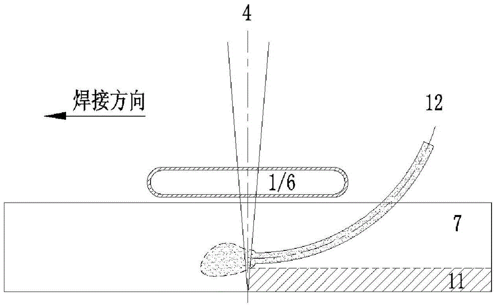
The invention provides a narrow gap laser welding protective method and a narrow gap laser welding protective device. The method comprises the steps of: in a welding process, blowing shielding gas into a welding narrow gap in a side blowing mode; sucking smoke generated in a suction mode and plasma air mass wrapped above a molten pool. By the method, the welding smoke can be removed from a welding groove, and the smoke can be prevented from accumulating on the side wall of the welding groove; and moreover, a shielding effect of plasma to laser is improved, absorptivity of the laser is enhanced, and wettability between welding materials is improved, so that the stability of the narrow gap laser welding is improved, welding defects are avoided, and the method is easy to promote in the real industrial production.

Description

technical field [0001] The invention relates to the field of welding technology, in particular to a welding seam protection method and device following narrow gap laser welding. Background technique [0002] While maintaining the high quality, high precision, and low deformation of laser self-fluxing welding, the narrow gap laser welding technology overcomes the difficulty in controlling the metallurgical process of the weld, the coarse grains of single-pass welding penetration, stress concentration, and residual stress. In most cases, it is a new laser welding technology with broad application prospects. In recent years, many scholars at home and abroad have carried out related research on narrow-gap laser welding technology. For example, Professor Li Lin of the University of Manchester used a 1KW fiber single-mode laser to weld 26mm titanium alloys in 15 passes in the laboratory to obtain low residual stress and tensile strength. Welding joints whose strength is greater t...

Claims


Application Information

Patent Timeline
Patent Type & Authority Applications(China)
IPC IPC(8): B23K26/70
Inventor 单飞虎巩水利陶军陈俐杨璟李嘉宁赵晓龙王翔宇
Owner AVIC BEIJING AERONAUTICAL MFG TECH RES INST
Learn More