
Pumping chamber of centrifugal pump

A technology of pressurized water chamber and centrifugal pump, applied in the field of centrifugal pump, can solve the problems of delamination and fracture, and the coating adhesion is not greatly improved, and achieve the effect of inhibiting wear, convenient processing, and optimizing internal flow

Active Publication Date: 2019-08-09
LANZHOU UNIVERSITY OF TECHNOLOGY
View PDF6 Cites 0 Cited by
  • Summary
  • Abstract
  • Description
  • Claims
  • Application Information

AI Technical Summary

Problems solved by technology

However, since this method only unilaterally changes the hardness or compressive strength of the material, the adhesion of the coating has not been greatly improved, so delamination and fracture often occur.

Method used


Image

  • Pumping chamber of centrifugal pump
  • Pumping chamber of centrifugal pump
  • Pumping chamber of centrifugal pump

Examples


Embodiment Construction

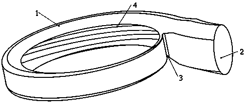
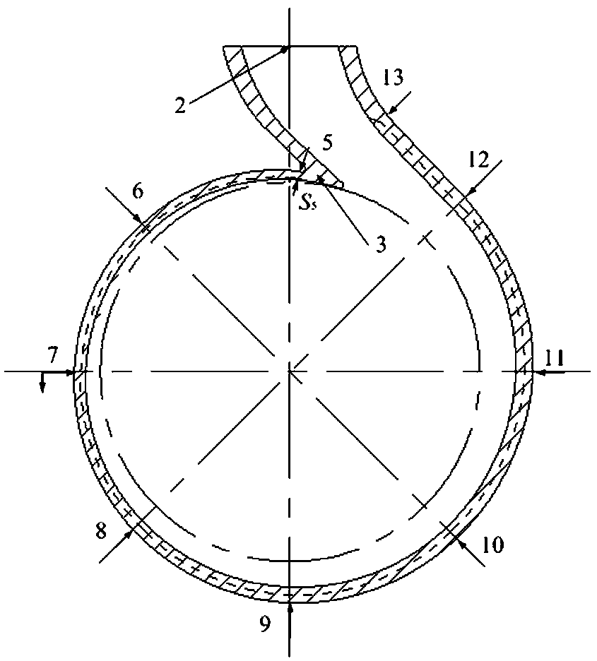
[0009] like figure 1 , figure 2 As shown, the present invention is a centrifugal pump pressurized chamber, comprising a pressurized chamber housing 1, an outlet 2 of the pressurized chamber, and a tongue 3 of the pressurized chamber. Groove 4 spreads along the pressurized water chamber partition tongue 3 to the direction of the pressurized water chamber outlet 2.

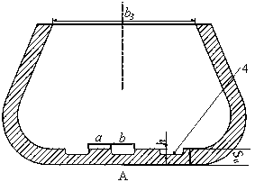
[0010] like figure 1 , figure 2 As shown, the pressure water chamber of the centrifugal pump of the present invention includes a pressure water chamber housing 1 , an outlet 2 of the pressure water chamber, a tongue 3 and a groove 4 in the pressure water chamber. The shape of the pressurized water chamber is spiral, and the cross-sectional shape of each flow is trapezoidal. The projection shape of the groove 4 on the plane is consistent with the shape of the flow channel of the pressure water chamber housing 1. The grooves are opened from the pressure water chamber partition tongue 3 and end at the ninth secti...


PUM


Abstract

The invention relates to a pumping chamber of a centrifugal pump, and aims to improve the operation stability and wear resistance of the centrifugal pump. The pumping chamber comprises a pumping chamber shell (1), a pumping chamber outlet (2) and a pumping chamber partition tongue (3), wherein a groove (4) is formed in the pumping chamber along the longitudinal direction and extends along the direction from the partition tongue (3) to the pumping chamber outlet (2). The inner wall of the pumping chamber is of unequal thickness, rectangular section grooves are longitudinally formed in the innerwall of the pumping chamber, and therefore, the structure can improve flow stability of a flow field, influence the movement state of solid particles in the centrifugal pump, improve the operation stability of the pump, inhibit the abrasion of the inner wall of the pumping chamber, and prolong the service life of the centrifugal pump. The pumping chamber is suitable for the fields such as electric power pumping irrigation engineering, petrochemical industry and mine metallurgy.

Description

technical field [0001] The invention relates to a centrifugal pump technology, in particular to a pressure water chamber technology capable of improving flow stability and inhibiting wear. Background technique [0002] The complex three-dimensional flow in the centrifugal pump and the resulting flow separation, vibration and cavitation, etc., which affect the stability of its operation, have always been research hotspots at home and abroad. In addition, under the condition of conveying solid-liquid two-phase flow, the erosion and wear of solid-phase particles will destroy the metal lubricating film on the surface of the flow-passing parts, and then form different shapes of furrows, holes or scale pits, etc., resulting in a significant decrease in unit efficiency , low reliability, shortened replacement cycle of over-current components, resulting in huge waste of energy and equipment. The wear and damage of the flow-passing parts of the centrifugal pump mainly occurs on the ...

Claims


Application Information

Patent Timeline
Patent Type & Authority Applications(China)
IPC IPC(8): F04D29/42F04D29/66
CPCF04D29/426F04D29/669
Inventor 申正精韩伟赵伟国郭荣宋启策权辉郭艳磊
Owner LANZHOU UNIVERSITY OF TECHNOLOGY
Learn More