
Inner sound quality improvement system caused by vehicle carbon tank

A sound quality and carbon canister technology, applied in the field of interior sound quality improvement systems, can solve problems such as high cost, complexity, and poor noise reduction effects

Pending Publication Date: 2019-08-09
CHINA AUTOMOTIVE ENG RES INST
View PDF0 Cites 3 Cited by
  • Summary
  • Abstract
  • Description
  • Claims
  • Application Information

AI Technical Summary

Problems solved by technology

[0004] At present, the national emission regulations have been upgraded from China V to China VI, and the technical requirements for the gasoline evaporation system are higher, especially for vehicles with supercharged engines, two carbon canister desorption pipelines will be equipped, one is through the carbon The canister solenoid valve is connected to the low-load desorption pipeline of the intake manifold, and the other is the high-load desorption pipeline connected to the air filter outlet pipe through the carbon canister solenoid valve, which will inevitably lead to a higher workload of the carbon canister solenoid valve. However, the high-speed opening and closing of the valve plate will cause a large pressure pulsation in the valve body and the desorption pipe, and at the same time, pulsating noise of the same frequency will be radiated in the car, especially during idling and low speed driving. Especially obvious, seriously affecting the sound quality characteristics of the vehicle
[0005] At present, the commonly used methods to reduce the vibration and noise in the car caused by the carbon canister solenoid valve are: 1) Optimizing the body and installation form of the carbon canister solenoid valve; High, the overall noise reduction effect is not very good

Method used


Image

  • Inner sound quality improvement system caused by vehicle carbon tank
  • Inner sound quality improvement system caused by vehicle carbon tank
  • Inner sound quality improvement system caused by vehicle carbon tank

Examples


no. 1 example

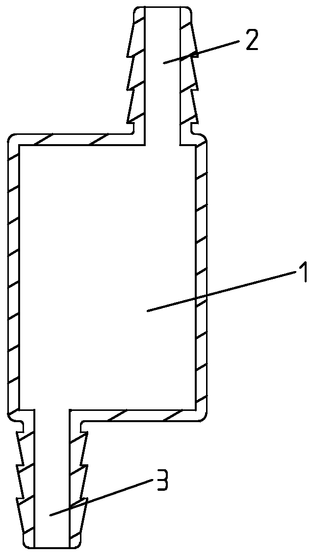
[0030] The first embodiment of the present invention, as attached figure 1 , the inner cavity of the body 1 is a pure cavity structure, and the centerline of the air inlet hole 2 and the centerline of the air outlet hole 3 are not on the same straight line. When the pressure pulsation passes through the inner cavity of the body 1, most of the kinetic energy can be attenuated, thereby effectively buffering and reducing the pulsation energy on the canister desorption tube, and finally reducing the pulsation noise inside the car when idling and low speed driving, improving Interior sound quality characteristics.

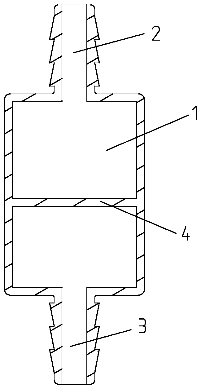
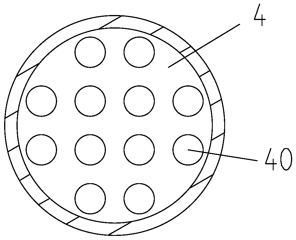
[0031] The second embodiment of the present invention, as attached figure 2 And attached image 3 As shown, the center line of the air inlet hole 2 and the air outlet hole 3 are on the same straight line, and a baffle plate 4 is provided in the cavity of the body 1, and a plurality of through holes 40 are distributed on the baffle plate 4 . The baffle plate 4 is dis...


PUM


Abstract

The invention discloses an inner sound quality improvement system caused by a vehicle carbon tank. The inner sound quality improvement system comprises a carbon tank solenoid valve and a carbon tank desorption pipe, an energy absorption device is arranged on the carbon tank desorption pipe, the carbon tank solenoid valve communicates with one end of the energy absorption device, and the carbon tank desorption pipe communicates with the other end of the energy absorption device. According to the inner sound quality improvement system, on the basis of not optimizing the structures of a carbon tank body and the carbon tank solenoid valve, meanwhile under the premise of without affecting the power, fuel economy and safety of a whole vehicle, an energy absorption structure is only needed to beadded on the transmission path to lower vibration in the vehicle, finally the fluctuating noise in the vehicle is lowered, the sound quality characteristics in the vehicle are improved, the operationis easy, the effect is obvious, and the cost of research and development is low.

Description

technical field [0001] The invention relates to the technical field of automobile NVH, in particular to an interior sound quality improvement system caused by an automobile carbon canister. Background technique [0002] With the rapid development and fierce competition in the automotive industry, consumers have higher and higher requirements for automotive products. They not only pursue power performance, fuel economy, and safety, but also pay attention to the characteristics of interior sound quality. [0003] The principle of pulsating noise in the car caused by the carbon canister solenoid valve: the opening and closing of the carbon canister solenoid valve transports the fuel vapor after absorbing impurities in the carbon canister to the engine intake system, and the opening and closing of the valve causes the valve body and desorption Pressure pulsation occurs on the pipeline, and the pulsation energy is transmitted to the body through the desorption tube to radiate pul...

Claims


Application Information

Patent Timeline
Patent Type & Authority Applications(China)
IPC IPC(8): F16L55/033F16L55/027F02M25/08
CPCF16L55/033F16L55/02709F02M25/08F02M25/0872
Inventor 陈永李沛然陈景昌杨喜岷刘洋山
Owner CHINA AUTOMOTIVE ENG RES INST
Learn More