
External cavity feedback spectrum combining device capable of adjusting output beam spectral width

An external cavity feedback, spectral beam combining technology, applied in the field of semiconductor lasers, can solve the problems of limited spectral width compression, sub-unit beam crosstalk, linear density limitations, etc. The effect of reducing the effect of thermal effects

Inactive Publication Date: 2019-08-09
XIHUA UNIV
View PDF5 Cites 3 Cited by
  • Summary
  • Abstract
  • Description
  • Claims
  • Application Information

AI Technical Summary

Problems solved by technology

[0004] At present, the methods of compressing the spectrum to synthesize the beam spectral width mainly include: 1. Increase the focal length of the conversion lens, but this method will increase the transmission path of the beam in the grating external cavity, resulting in easy beam crosstalk between sub-units; 2. Increase the grating line Density, however, the grating is the main dispersion element of the spectrum beam combining system, changing its linear density will affect its diffraction efficiency, and the linear density is limited by the laser wavelength; 3. Reduce the distance between subunits, but due to the limitation of semiconductor laser packaging technology, Limited ability to compress spectral width by reducing subunit spacing
In the case of limited packaging technology, an external optical system is used to compress the beam spacing. The existing technology uses 4f optical imaging systems and prisms to compress the beam spacing, but the lenses and prisms in the optical system have dispersion effects on beams with different wavelengths. , it is easy to cause the beam divergence angle to increase and reduce the beam combining efficiency

Method used


Image

  • External cavity feedback spectrum combining device capable of adjusting output beam spectral width
  • External cavity feedback spectrum combining device capable of adjusting output beam spectral width
  • External cavity feedback spectrum combining device capable of adjusting output beam spectral width

Examples


Embodiment Construction

[0038] In order to make the purpose, technical solutions and advantages of the present invention clearer, the technical solutions in the present invention are clearly and completely described below. Apparently, the described embodiments are part of the embodiments of the present invention, not all of them. Based on the embodiments of the present invention, all other embodiments obtained by persons of ordinary skill in the art without creative efforts fall within the protection scope of the present invention.

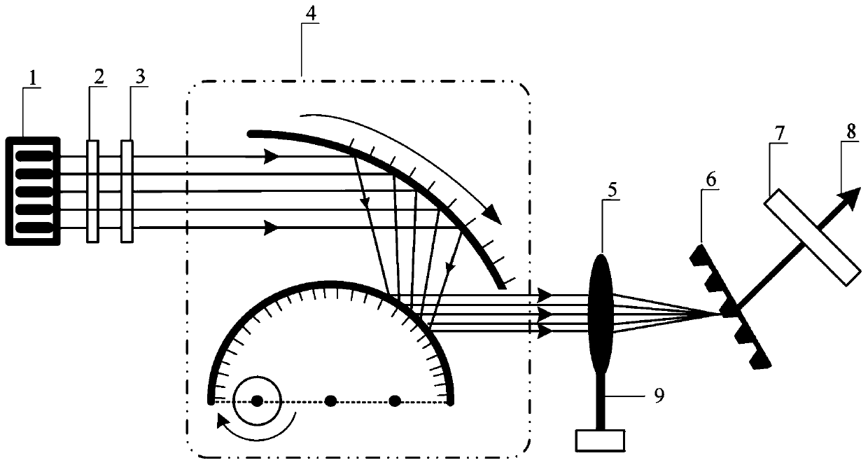
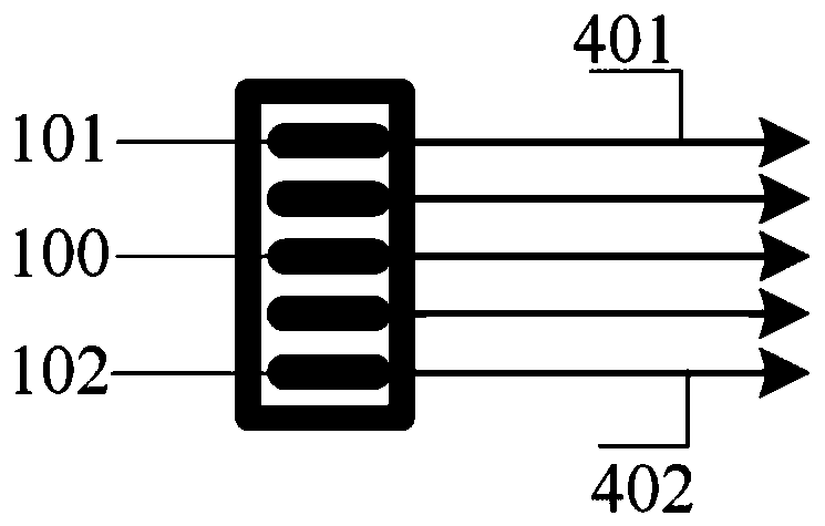
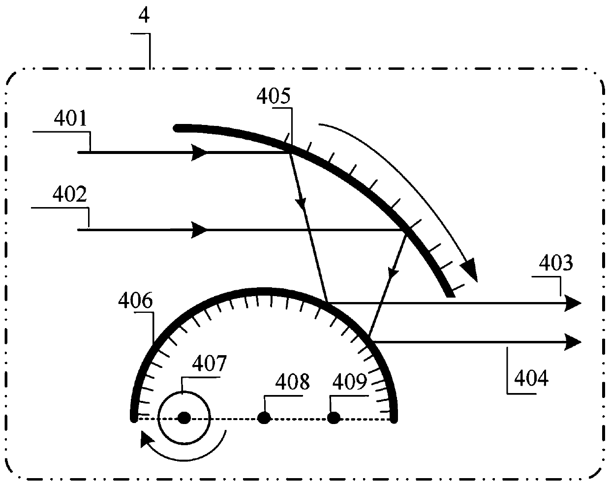
[0039] figure 1As an embodiment of the present invention, a spectral beam combining device that uses a rotatable concave spherical reflector and a convex spherical reflector to realize multiple reflections to compress the spectral width can overcome the reduction of light beams of different frequencies by the existing spectral width compression device. The problem of inconsistent beam magnification, the device includes semiconductor laser array light source 1, fast axis ...


PUM


Abstract

The invention provides an external cavity feedback spectrum combining device capable of adjusting output beam spectral width. The device includes a concave spherical mirror capable of rotating about the spherical center and a convex spherical mirror fixed in position, wherein the concave spherical mirror is used for reflecting and gathering incident parallel beams to the convex spherical mirror, the convex spherical mirror is used for reflecting and collimating the incident parallel beams reflected and gathered by the concave spherical mirror to form parallel light output, focal points of theconcave spherical mirror and the convex spherical mirror coincide, the curvature radius R of the concave spherical mirror is larger than the curvature radius r of the convex spherical mirror, and a spherical center interval of the concave spherical mirror and the convex spherical mirror is (R-r) / 2. The device is advantaged in that a limitation that a conventional lens and prism shaping have a certain divergence effect on different frequency beams is solved.

Description

technical field [0001] The invention relates to the technical field of semiconductor lasers, in particular to an external cavity feedback spectrum beam combiner capable of adjusting the spectral width of an output beam. Background technique [0002] High-power semiconductor lasers have the advantages of light weight, maintenance-free and high reliability, and have broad application prospects in the fields of intelligent equipment manufacturing, medical treatment and communication. However, due to the special principle and structure of semiconductor lasers, there is a trade-off between output power and beam quality, that is, the beam quality will deteriorate while pursuing high power. [0003] The key technology to solve this problem is to package semiconductor lasers into an array or stack structure, and then use spectral beam combining technology to achieve single beam output. Spectrum beam combining technology often uses a grating as a dispersive element, and the oscillat...

Claims


Application Information

Patent Timeline
IPC IPC(8): H01S5/14H01S5/40
CPCH01S5/141H01S5/4012
Inventor 吴真杨盛凯徐勇根赵亮
Owner XIHUA UNIV
Learn More