
Novel motor and energy output method thereof

An energy output and electric energy output technology, applied in the field of new motor and its energy output, can solve the problems of limiting the maximum speed and power of the motor, high magnetic reactance, etc., and achieve the effect of low energy consumption and simple structure

Inactive Publication Date: 2019-08-09
王睿
View PDF0 Cites 0 Cited by
  • Summary
  • Abstract
  • Description
  • Claims
  • Application Information

AI Technical Summary

Problems solved by technology

In this way, when the motor is running at high speed, the alternating current produces a high magnetic reactance in the coil, which limits the maximum speed and power of the motor.

Method used


Image

  • Novel motor and energy output method thereof
  • Novel motor and energy output method thereof
  • Novel motor and energy output method thereof

Examples


Embodiment Construction

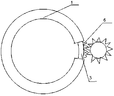
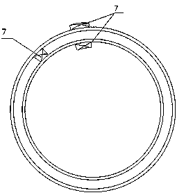
[0016] The implementation of the present invention will be described more fully below in conjunction with accompanying drawings 1, 2 and 3. Obviously, the described embodiments are only a part of the embodiments of the present invention, rather than all of them. Based on the embodiments of the present invention, other examples obtained by persons of ordinary skill in the art without any creative efforts are within the protection scope of the present invention.

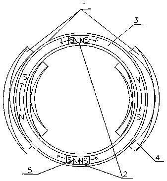
[0017] Referring to accompanying drawing 1, adopt the imitation magnetic monopole subgroup (2) of the magnetic coil group (1) of two electromagnetic coils (4) and two imitation magnetic monopoles (5) fixed on the annular support (3) ) A new type of motor composed of. After electrification, a circular magnetic force flow is generated in the magnetic coil group (1). The imitation magnetic monopole (5) generates repulsive force with one end and suction force at the other end in the magnetic coil group (1), thereby pushin...


PUM


Abstract

The invention relates to a novel motor. An annular hollow ring is defined by more than one hollow electromagnetic coil (4). After the electromagnetic coils (4) are energized, an annular magnetic lineof force flow is formed in the annular hollow ring. More than one imitated magnetic monopole (5) is fixed to an annular bracket (3) in the hollow ring. The imitated magnetic monopoles (5) move the annular bracket (3) in the annular hollow ring in one direction by means of the characteristic that the imitated magnetic monopoles move in one direction of the magnetic line of force. Thus, there is nocurrent and magnetic field transformation in operation, so ultrahigh speed and power can be obtained. The theoretical linear velocity is the speed of light when the centrifugal force limit of the annular bracket (3) and the system frictional resistance are not taken into consideration. Because of the difference in structure from a conventional motor, the method provides, by way of examples, two alternative ways for energy output including mechanical output and electrical energy output. The novel motor of the invention can also use other ways to output energy.

Description

[0001] Technical field: [0002] electric motor [0003] Background technique: [0004] The existing motor drive methods are two sets of magnetic force generators, one of which must be an electromagnetic coil, and the current direction, phase and current intensity of the coil are changed through various current reversing devices, thereby changing the distribution of the internal magnetic force lines of the motor to control The force and direction between the two sets of magnetic force generators make the drive output end of the motor move in the same direction. In this way, when the motor is running at high speed, the alternating current produces a high magnetic reactance in the coil, which limits the maximum speed and power of the motor. [0005] Invention content: [0006] The present invention is a new type of motor. An annular hollow ring is composed of more than one hollow electromagnetic coil (4). After the electromagnetic coil (4) is energized, it forms a flow leading ...

Claims


Application Information

Patent Timeline
IPC IPC(8): H02K1/12H02K1/22H02K3/28H02K3/47
CPCH02K1/12H02K1/22H02K3/28H02K3/47
Inventor 不公告发明人
Owner 王睿
Learn More