Wire transmission walking structure based on underactuated decoupling

A wire-driven, under-actuated technology, applied in manipulators, program-controlled manipulators, manufacturing tools, etc., can solve the problems of muscle damage, worker fatigue, and high frequency of motor position feedback, reducing costs, high system reliability, and reducing corresponding requirements. and the effect of system feedback frequency

Pending Publication Date: 2019-08-16
上海傲鲨智能科技有限公司
View PDF0 Cites 1 Cited by
  • Summary
  • Abstract
  • Description
  • Claims
  • Application Information

AI Technical Summary

Problems solved by technology

[0002] Many workers in the industrial environment need to use heavy tools or overhead station operations, tasks on the front of the body, etc. Long-term repetition and high-intensity exercise will cause a series of safety and efficiency issues such as worker fatigue and muscle damage.
[0003] The existing steel wire drive underactuation technology uses one motor to drive two degrees of freedom (upward movement of the shoulder joint is used as the driving force degree of freedom, and shoulder joint abduction and adduction is the underactuated degree of freedom). When the driving motor is far away from the driving joint point, the driving In the upward movement of the shoulder joint, when the steel wire moves through the abduction and adduction joint of the shoulder, kinematic coupling usually occurs, and the coupling position is judged by the abduction and adduction position sensor of the shoulder joint and the main wire reel position sensor of the motor. Poor, through the rotation of the motor to do motion decoupling, this kind of method belongs to software decoupling, usually have higher requirements on the position feedback frequency of the corresponding encoder of the motor, the cost of the system is higher, so there is an urgent need for a method based on underactuation Decoupled wire drive positioning structure to solve existing problems

Method used


Image

  • Wire transmission walking structure based on underactuated decoupling
  • Wire transmission walking structure based on underactuated decoupling
  • Wire transmission walking structure based on underactuated decoupling

Examples


Embodiment Construction

[0035] The present invention will be further described below in conjunction with accompanying drawing:

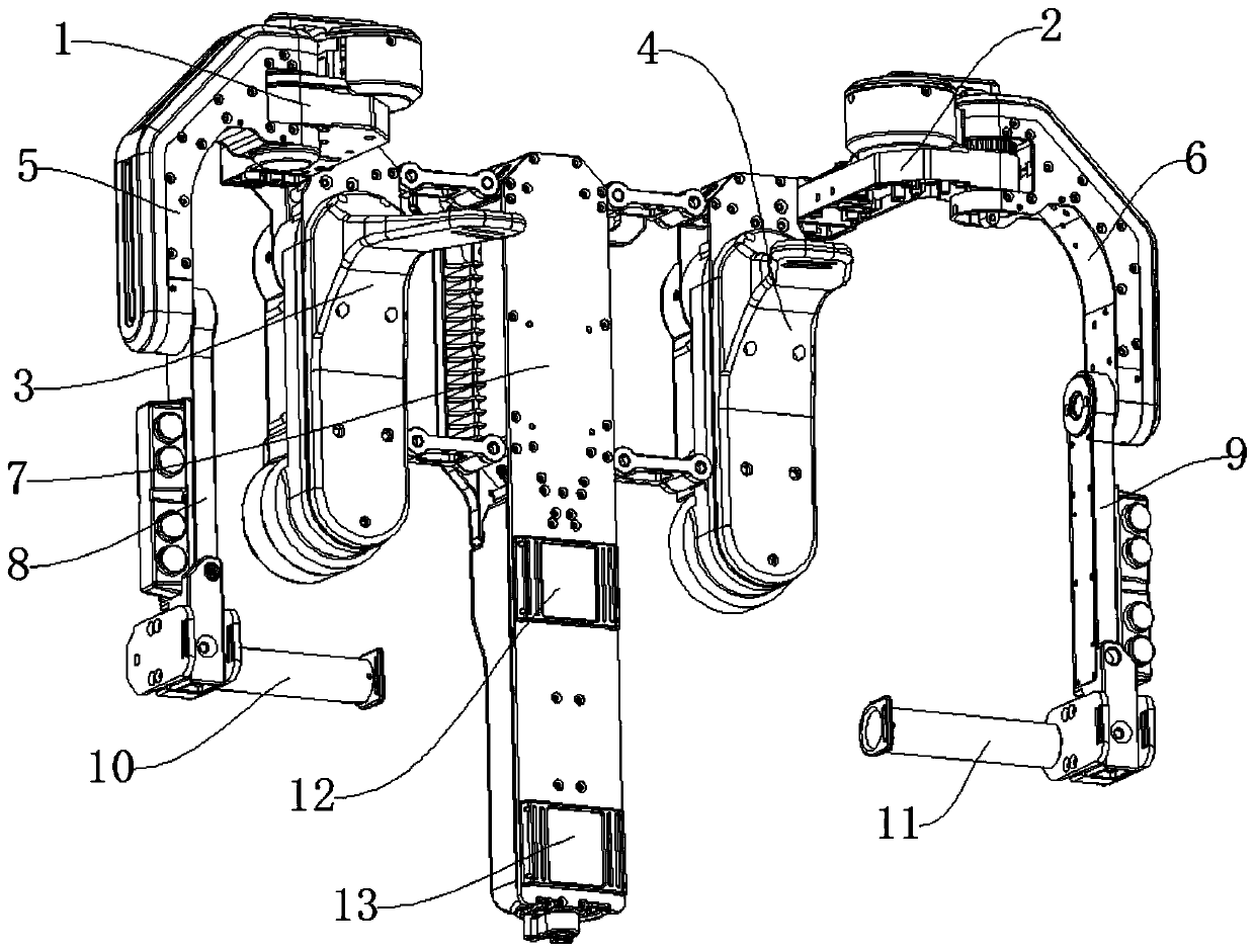
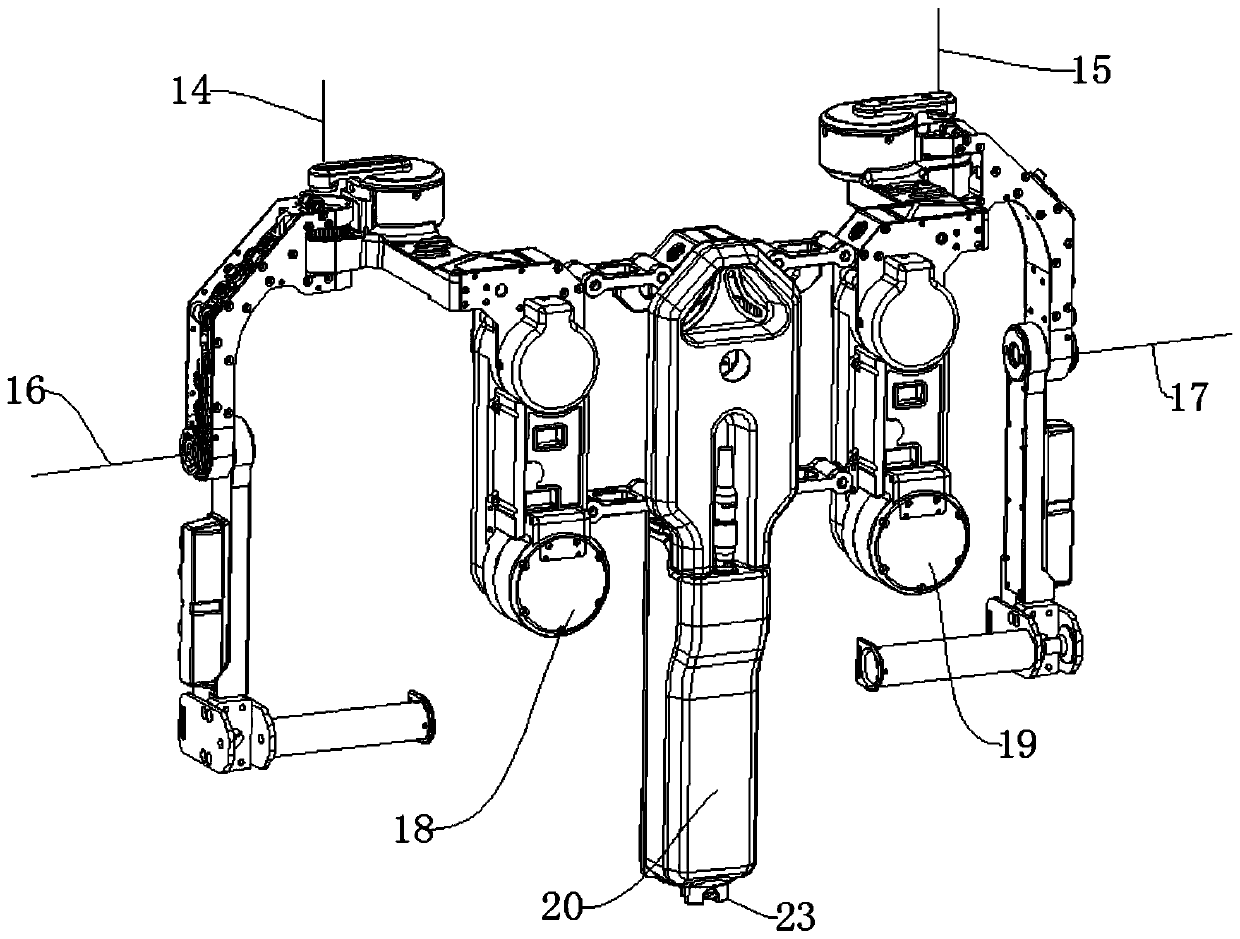
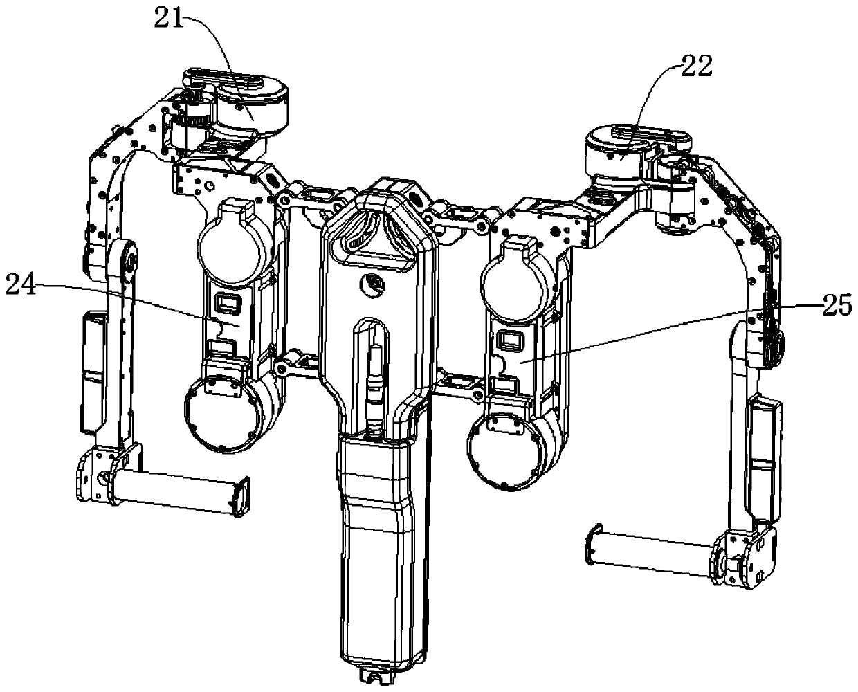
[0036] like Figure 1-Figure 6As shown, a wire transmission walking structure based on underactuated decoupling includes a backrest board 7, a right shoulder backrest 3 and a left shoulder backrest 4, and a right shoulder backrest 3 is provided on one side of the backrest board 7, Backrest board 7 is provided with left shoulder back cushion 4 on one side away from right shoulder back cushion 3, and right side shoulder back cushion 3 upper side is provided with right shoulder wire transmission pulley base 1, and right side shoulder wire transmission pulley base 1 One side is provided with the right shoulder abduction action arm pulley base 5, the right side shoulder abduction action arm pulley base 5 lower end is provided with the lifting action arm 8 on the right shoulder, lifts the action arm 8 lower end on the right shoulder and is provided with Right side elbow bracket ...


PUM


Abstract

The invention discloses a wire transmission walking structure based on underactuated decoupling. The structure comprises a backup plate, a right side shoulder cushion and a left side shoulder cushion;and the right side shoulder cushion is arranged on one side of the backup plate. The structure has the following beneficial effects: through mechanical walking of steel wires, the motion coupling problems of outward unfolding and inward folding of shoulder joints are decoupled; when a motor driving end is far from action joint points of upward lifting of shoulder joints, the motor driving end still can be directly driven through a steel wire of a motor without being interfered by passive or active outward unfolding motions of the shoulder joints; one motor controls one active degree of freedom without interfering another underactuated degree of freedom, so that corresponding system requirements and the system feedback frequency are reduced, and the cost is reduced; and due to hardware decoupling, the delay caused by the algorithm in software compensation is not generated, and the system reliability is high.

Description

technical field [0001] The invention relates to the fields of industrial automation, logistics handling, military use, civil use, medical treatment and sports, and in particular relates to a wire drive positioning structure based on underactuated decoupling. Background technique [0002] Many workers in the industrial environment need to use heavy tools or overhead station operations, front-side tasks, etc., long-term repetitive and high-intensity exercise will cause a series of safety and efficiency issues such as worker fatigue and muscle damage. [0003] The existing steel wire drive underactuation technology uses one motor to drive two degrees of freedom (upward movement of the shoulder joint is used as the driving force degree of freedom, and shoulder joint abduction and adduction is the underactuated degree of freedom). When the driving motor is far away from the driving joint point, the driving In the upward movement of the shoulder joint, when the steel wire moves th...

Claims


Application Information

Patent Timeline
IPC IPC(8): B25J9/00
CPCB25J9/0006
Inventor 徐振华
Owner 上海傲鲨智能科技有限公司
Why Eureka
Try Eureka