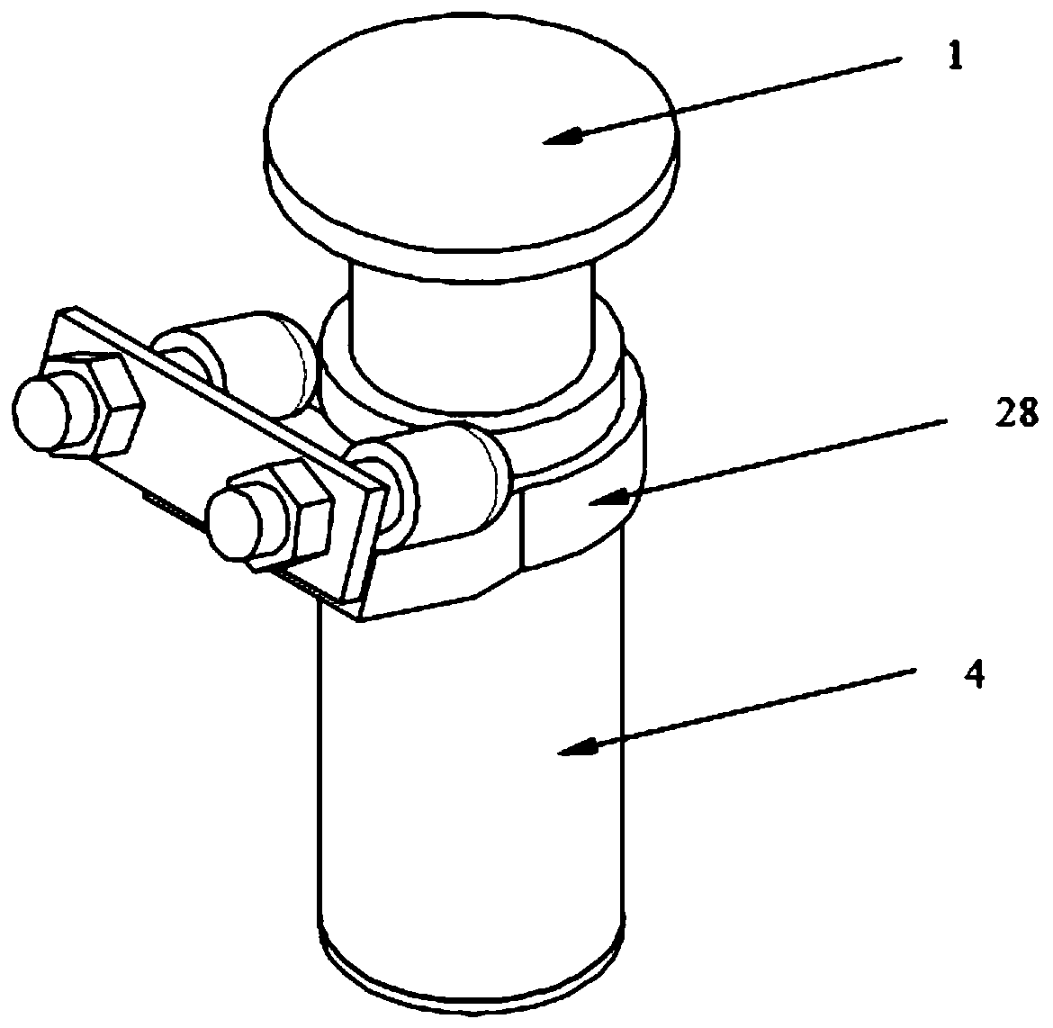
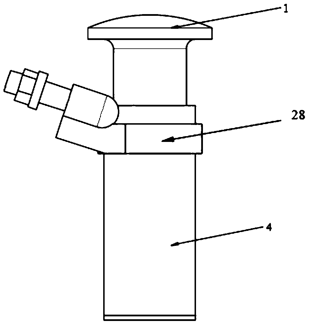
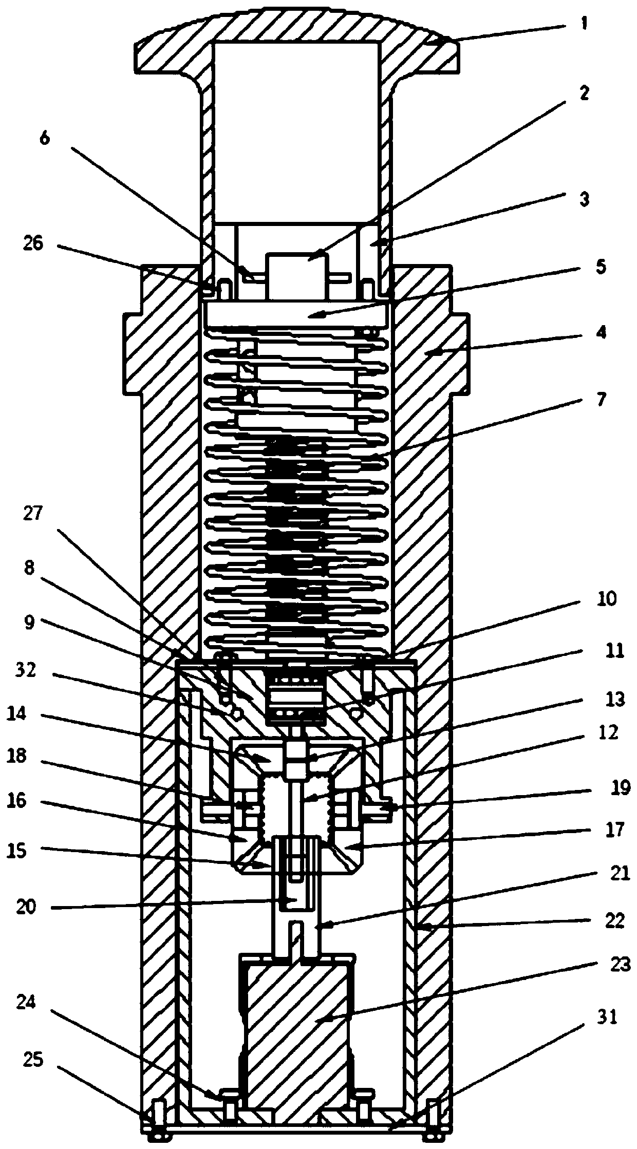
Freight train self-storage energy retarder

A technology for freight trains and deceleration jacks, applied in transportation and packaging, railway car body parts, machines/engines, etc., can solve problems such as energy waste, heat dissipation, etc., and achieve reduced impact peak loads, reduced vibration, and high strength Effect

Inactive Publication Date: 2019-08-16
SOUTHWEST JIAOTONG UNIV
View PDF11 Cites 9 Cited by
  • Summary
  • Abstract
  • Description
  • Claims
  • Application Information

AI Technical Summary

Problems solved by technology

[0004] During the deceleration process of the train, it will work on the deceleration jack, but in the prior art, the work done by the train on the deceleration jack is not utilized, and all of it is converted into heat energy and dissipated into the air, resulting in a large amount of energy waste

Method used


Image

  • Freight train self-storage energy retarder
  • Freight train self-storage energy retarder
  • Freight train self-storage energy retarder

Examples


Embodiment Construction

[0044] All features disclosed in this specification, or steps in all methods or processes disclosed, may be combined in any manner, except for mutually exclusive features and / or steps.

[0045] Combine below Figure 1 ~ Figure 4 The present invention will be described in detail.

[0046] A self-storage energy deceleration roof for freight trains includes a roof 1, a roof base 4 and a fixing device, and also includes a power generation and storage device and a ball screw 2. The ball screw 2 is equipped with a nut 5 , and the nut 5 cooperates with the ball screw 2 to convert the linear motion of the nut 5 into the rotational motion of the ball screw 2 . The top 1 is welded to the nut top connector 3, the nut top connector 3 and the nut 5 are connected by bolt I, the ball screw 2 is covered with a spring 7, the spring 7 is located between the nut 5 and the fixing device, and the spring 7 The diameter is smaller than the diameter of the nut 5 . Described power generation storag...


PUM


Abstract

The invention belongs to the field of retarders, and specifically relates to a freight train self-storage energy retarder. The problem that energy released during deceleration of an existing train isnot recovered is aimed at. The invention discloses the freight train self-storage energy retarder. The technical scheme is that the freight train self-storage energy retarder comprises a top (1), a top seat (4), and a fixing device and further comprises a ball screw (2) and a power generating and storing device, the ball screw (2) is provided with a nut (5) in a matching mode, the top (1) is fixedly connected with the nut (5), a spring (7) sleeves the ball screw (2), the spring (7) is located between the nut (5) and the fixing device, the power generating and storing device comprises a generator (23) and an energy storage device, the fixing device and the top seat (4) are connected, the lower end of the ball screw (2) is rotatably connected with the fixing device, and the lower end of theball screw (2) is connected with a rotating shaft of the generator (23). The freight train self-storage energy retarder is suitable for decelerating trains.

Description

technical field [0001] The invention belongs to the field of deceleration tops, in particular to a self-storage energy deceleration top for freight trains. Background technique [0002] The deceleration top is a kind of internal hydraulic oil, installed on the inner or outer side of the rail, through the contact of the sliding cylinder and the wheel, the internal hydraulic oil is squeezed to perform braking work on the vehicle wheel to play a role in deceleration A speed control device. Its working principle is: [0003] When the vehicle passes through the decelerator, its wheel set travel speed is lower than the critical speed set by the decelerator. At this time, there will be no large pressure difference between the upper and lower chambers of the sliding cylinder, and the speed valve will be kept open. state, the oil in the upper chamber of the sliding cylinder will flow to the lower chamber through the passage of the speed valve, because the upper chamber of the slidi...

Claims


Application Information

Patent Timeline
Patent Type & Authority Applications(China)
IPC IPC(8): B61K7/08F03G7/00
CPCB61K7/08F03G7/00
Inventor 吴小平陈诗伟漆令飞吴舜尧胡江来刘晓东何都文常锟
Owner SOUTHWEST JIAOTONG UNIV
Why Eureka
Try Eureka