


Quick Research
Generate reliable direction feasibility study reports for your R&D in just a few steps.

Technical Q&A
Discover and master advanced knowledge NOW. Basics, ideas, possibilities, all at once.

Find Solutions
As an expert in R&D theories, this can generate solutions to your technical problems instantly.

Evaluate Feasibility
Analyze your overall solution with one click, know your potential R&D risks in advance.

Monitor Landscape
Get weekly tech updates, stay abreast of the latest tech innovations and key insights.
Vertical automatic clutch gear shifting structure
An automatic clutch, clutch mechanism technology, applied in the direction of automatic clutch, clutch, transmission control, etc., can solve the problems of high production cost and maintenance cost, short service life, large shift impact force, etc., to reduce the production cost and The effect of maintenance cost, extended service life, and reduced shift shock
- Summary
- Abstract
- Description
- Claims
- Application Information
AI Technical Summary
Problems solved by technology
Method used
Image

Examples
Embodiment 2
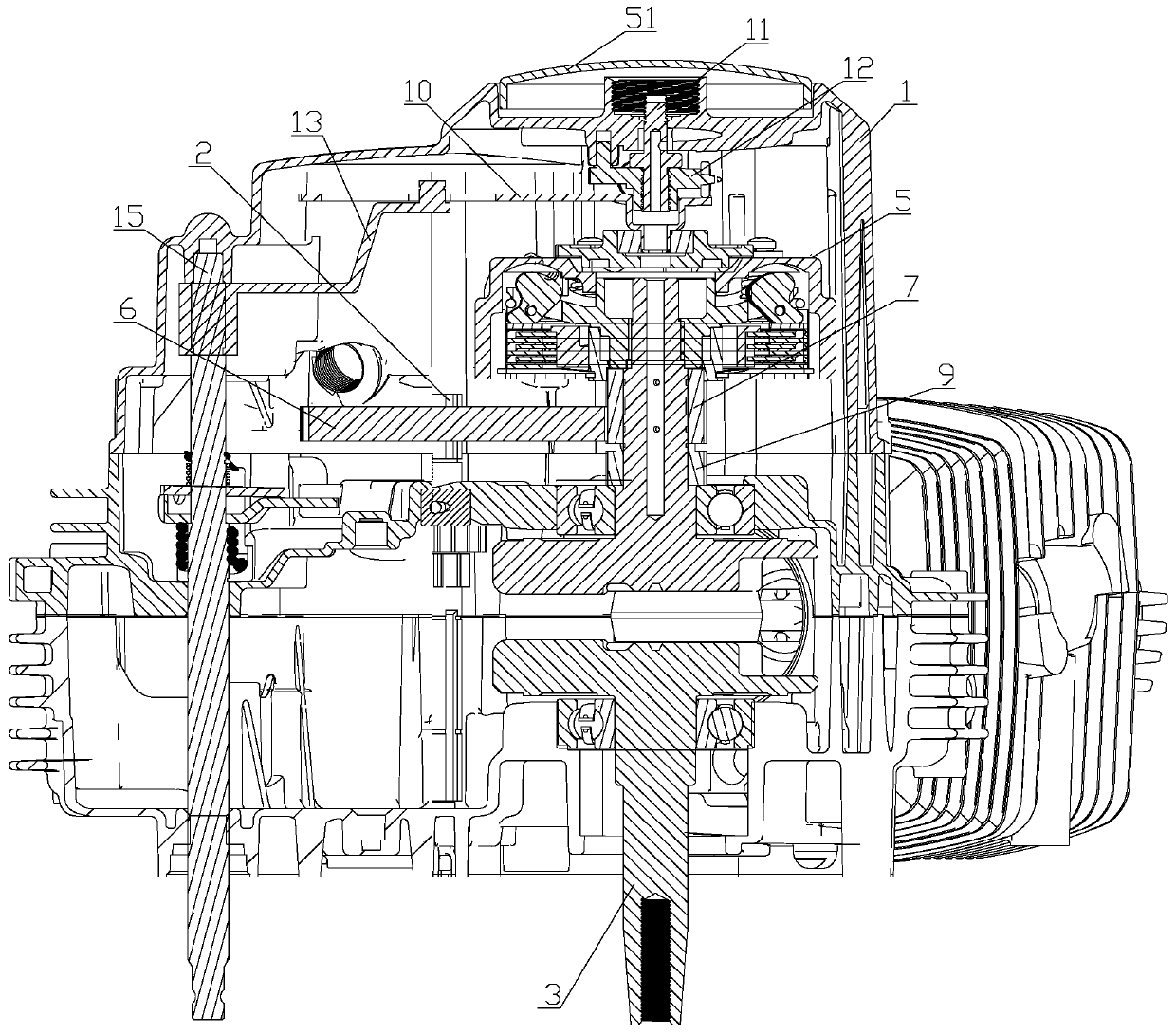
[0027] Embodiment 2, a vertical automatic clutch shifting structure, comprising a crank case cover 1, a transmission main shaft 2, a crank connecting rod assembly 3 and a clutch mechanism 5. The transmission main shaft 2 is sleeved with driven teeth 6, so The driven tooth 6 meshes with the primary driving tooth 7, the clutch mechanism 5 and the primary driving tooth 7 are arranged on the crank connecting rod assembly 3, and the primary driving tooth 7 is located at the fixed position of the clutch mechanism 5. Inside the core sleeve 8; an organic oil pump active tooth 9 is arranged below the primary active tooth 7, and the oil pump active tooth 9 is sleeved on the crank connecting rod assembly 3;
[0028] The clutch mechanism 5 is provided with a separation cam plate 10 at the upper end, a separation tappet body 12 is provided above the separation cam plate 10 through an adjusting bolt 11, a separation arm 13 is provided on the separation cam plate 10, and the separation arm 13 T...
Embodiment 3
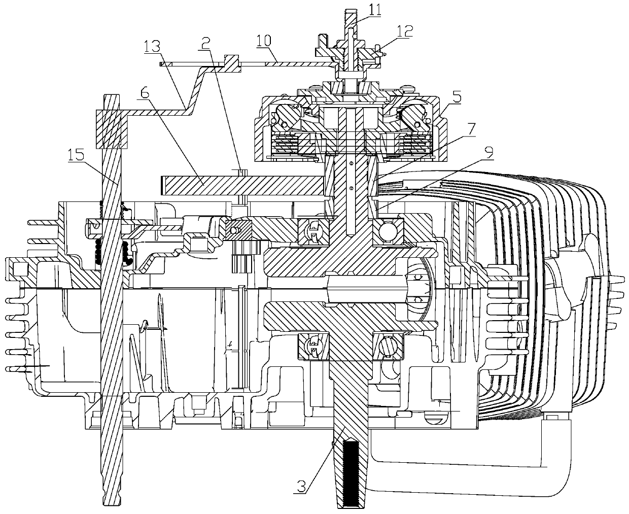
[0031] Embodiment 3, a vertical automatic clutch shifting structure, comprising a crank case cover 1, a transmission main shaft 2, a crank connecting rod assembly 3, and a clutch mechanism 5. The transmission main shaft 2 is sleeved with driven teeth 6, so The driven tooth 6 meshes with the primary driving tooth 7, the clutch mechanism 5 and the primary driving tooth 7 are arranged on the crank connecting rod assembly 3, and the primary driving tooth 7 is located at the fixed position of the clutch mechanism 5. Inside the core sleeve 8; an organic oil pump active tooth 9 is arranged below the primary active tooth 7, and the oil pump active tooth 9 is sleeved on the crank connecting rod assembly 3;
[0032] The clutch mechanism 5 is provided with a separation cam plate 10 at the upper end, a separation tappet body 12 is provided above the separation cam plate 10 through an adjusting bolt 11, a separation arm 13 is provided on the separation cam plate 10, and the separation arm 13 ...
PUM
 Abstract
Description
Claims
Application Information
 - R&D Engineer
- R&D Manager
- IP Professional
- Industry Leading Data Capabilities
- Powerful AI technology
- Patent DNA Extraction
Browse by: Latest US Patents, China's latest patents, Technical Efficacy Thesaurus, Application Domain, Technology Topic, Popular Technical Reports.
© 2024 PatSnap. All rights reserved.Legal|Privacy policy|Modern Slavery Act Transparency Statement|Sitemap|About US| Contact US: help@patsnap.com