
Optimal Design Method of Circular Porous Thermal Protection Material

A heat protection material and optimized design technology, applied in the aerospace field, can solve the problems of not taking into account hole-hole interference, reducing model prediction accuracy, not taking into account high-order modal scattering, etc., to achieve light weight, suppress disturbance intensity and pulsation Pressure amplitude, effect of simple structure

Active Publication Date: 2021-10-29
BEIJING INSTITUTE OF TECHNOLOGYGY
View PDF2 Cites 0 Cited by
  • Summary
  • Abstract
  • Description
  • Claims
  • Application Information

AI Technical Summary

Problems solved by technology

It should be pointed out that the above theoretical models are derived based on the acoustic characteristics of a single hole, and do not take into account the high-order modal scattering caused by the solid wall at the opening, nor the interference between holes, which reduces the prediction accuracy of the model

Method used


Image

  • Optimal Design Method of Circular Porous Thermal Protection Material
  • Optimal Design Method of Circular Porous Thermal Protection Material
  • Optimal Design Method of Circular Porous Thermal Protection Material

Examples


Embodiment 1

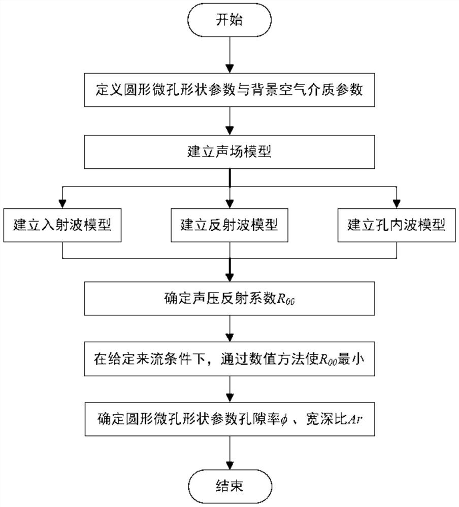
[0058] Such as figure 1 As shown, the optimal design method of the circular porous thermal protection material disclosed in this embodiment, the specific implementation steps are as follows:

[0059] Step 1: Define the shape parameters of the circular micropore and the parameters of the background air medium.

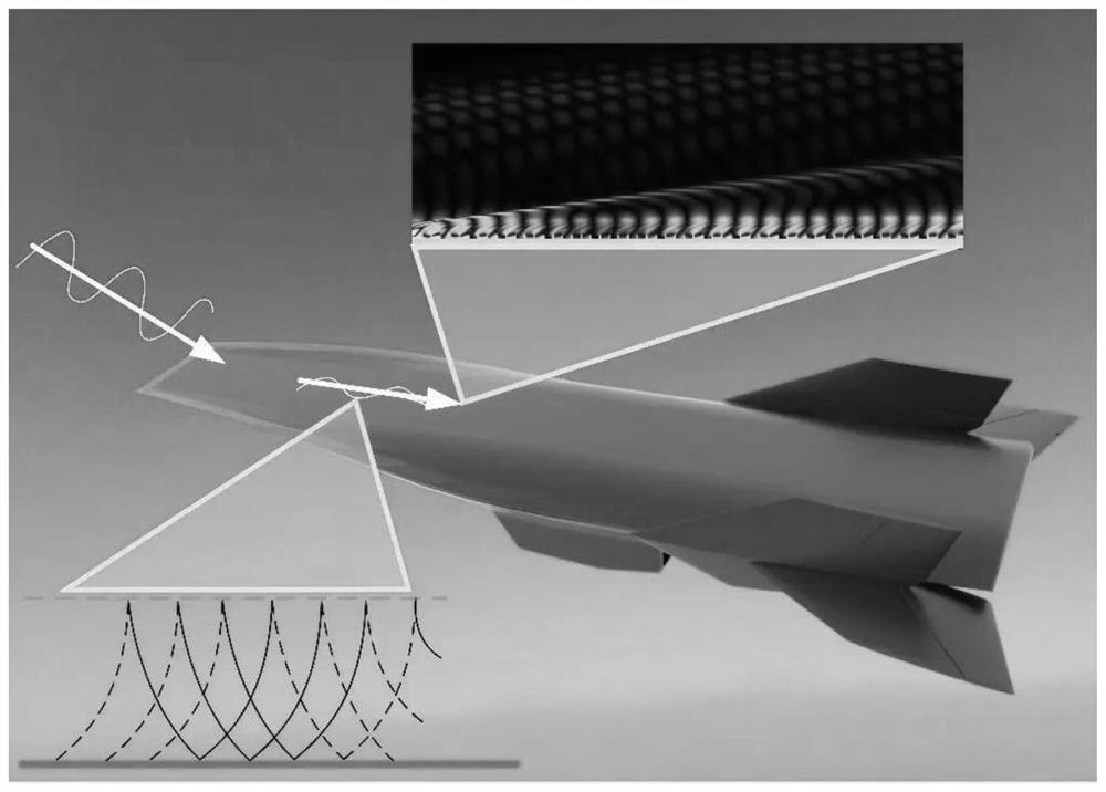
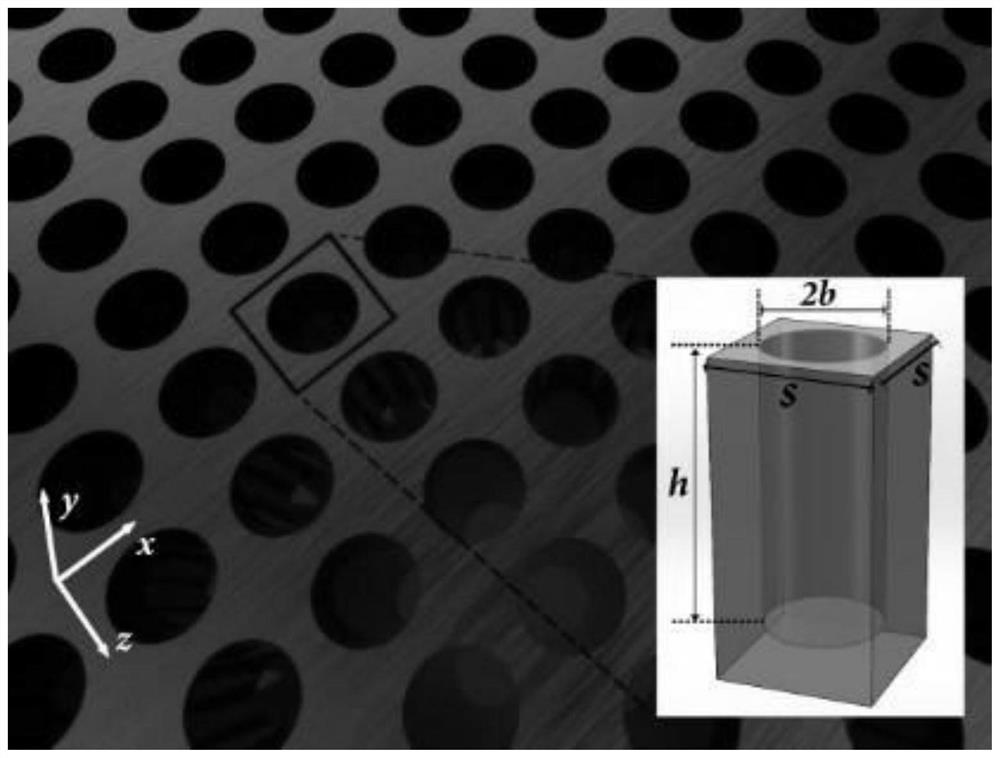
[0060] figure 2 The circular porous thermal protection material applied on the surface of a hypersonic vehicle, such as image 3 , is composed of a number of circular micro-holes regularly distributed periodically, the y-direction is defined as the pore depth direction, and the material surface plane perpendicular to the pore-depth direction is defined as the xz plane, and the radius is regularly distributed on the xz plane with s as the period b. A circular micropore with a hole depth of h. The dimensionless geometric parameter porosity φ is expressed by the above parameters as φ=πb 2 / s 2 , the dimensionless geometric parameter aspect ratio Ar is expressed as Ar...


PUM


Abstract

The invention discloses an optimal design method for a circular porous thermal protection material, which relates to an optimal design method for a circular porous thermal protection material that suppresses unstable waves of the Mack second mode in a boundary layer, and belongs to the field of aerospace. The realization method of the present invention is as follows: defining the shape parameter of the circular microhole and the parameter of the background air medium. Establish the sound field model and determine the sound pressure reflection coefficient in the sound field model. The sound field model includes an incident wave model, a reflected wave model and an in-hole wave model. The sound pressure reflection coefficient |R of order 0,0 is optimized by numerical method 00 |Minimum, determine the geometric parameters of the circular micropores, and obtain a porous thermal protection material that meets the purpose of thermal protection. The optimized porous thermal protection material that meets the purpose of thermal protection is applied in the field of thermal protection, so that the optimized circular porous thermal protection material can effectively avoid the heat flow peak in the flow transition zone, and keep the thermal load in the hypersonic incoming flow in the layer The thermal load transition in the flow area can achieve the purpose of thermal protection.

Description

technical field [0001] The invention relates to an optimal design method for a novel circular porous thermal protection material, in particular to an optimal design method for a circular porous thermal protection material that suppresses unstable waves of the Mack second mode in a boundary layer, and belongs to the field of aerospace. Background technique [0002] With the vigorous development of the aerospace industry, it puts forward higher and higher requirements for the thermal protection of high-speed aircraft. One of the main technical ideas for thermal protection is to reduce the thermal load of the aircraft by suppressing the transition of the boundary layer. This is because the flow state of the boundary layer has a significant impact on the aerodynamic and thermal environment of the hypervehicle. The aerodynamic heating in the turbulent flow area is much greater than that in the laminar flow area. The heat flow peak generally appears in the flow transition zone, wh...

Claims


Application Information

Patent Timeline
Patent Type & Authority Patents(China)
IPC IPC(8): G06F30/23G06F30/17G06F111/04G06F111/10G06F119/08
CPCG06F2119/08G06F30/17G06F30/20
Inventor 赵瑞张新昕魏昊功温志涌
Owner BEIJING INSTITUTE OF TECHNOLOGYGY
Learn More