Three-phase three-dimensional non-circular transformer body structure

A non-circular, transformer technology, applied in the field of transformers, can solve the problems of reducing no-load current and third harmonic, increasing no-load loss of iron core materials, increasing the weight of coil wire materials, etc., to achieve low no-load loss and manufacturing costs. Low, energy-efficient performance

Pending Publication Date: 2019-08-16
BAODING TIANWEI GRP JIANGSU WUZHOU TRANSFORMER
View PDF0 Cites 0 Cited by
  • Summary
  • Abstract
  • Description
  • Claims
  • Application Information

AI Technical Summary

Problems solved by technology

Transformers with a planar circular stacked core structure can basically meet the energy efficiency requirements of S11 type. It is also the structure adopted by most transformer manufacturers at present. Due to its structural characteristics, it is difficult to make major breakthroughs in reducing losses and saving materials. , although it can also meet the energy efficiency requirements of S13 type, but the material cost is relatively high
At present, the mainstream structure of S13 products is a three-dimensional triangular transformer, and the structure of the three-dimensional triangular circular iron core is as follows figure 2 , A, B, C three-phase iron cores and coils are symmetrically arranged in a square shape, so that the three-phase magnetic circuits are completely symmetrical and balanced, and the harmonics have paths in their respective phases, which reduces the no-load current and the third harmonic. At the same time, the structure Compact, the cross-sectional area of ​​the iron yoke is half of the stacked iron core, the magnetic circuit L1=L2=L3, the weight of the iron core is lighter under the same cross-sectional area S, and the no-load loss is reduced, but because the coils are distr

Method used


Image

  • Three-phase three-dimensional non-circular transformer body structure
  • Three-phase three-dimensional non-circular transformer body structure
  • Three-phase three-dimensional non-circular transformer body structure

Examples


Example Embodiment

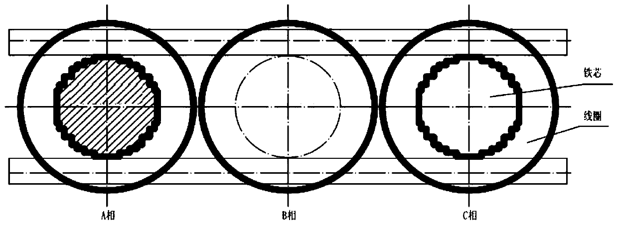
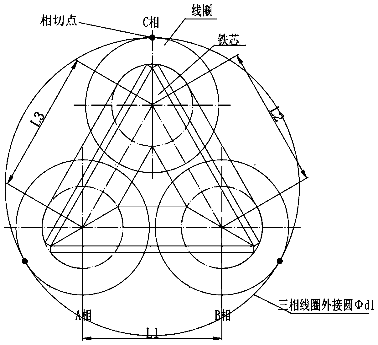
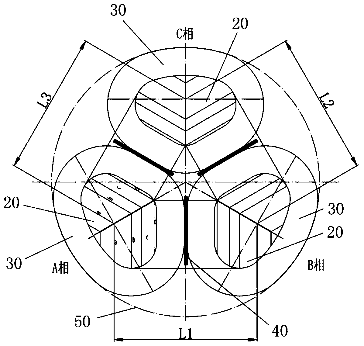
[0026] As shown in 3, a three-phase three-dimensional non-circular transformer body structure of the present invention includes an iron core and a coil assembly, the iron core includes three iron core legs 20, and the three iron core legs 20 have the same structural size, and The three iron core columns 20 are all arranged perpendicular to the horizontal plane and parallel to each other. The horizontal cross-sections of the three iron core columns 20 are all non-circular shapes. The horizontal cross-sections of the three iron-core columns 20 each have an arc-shaped side. The coil set includes three coils 30, the three coils 30 respectively surround the three iron core posts 20, and the three coils 30 are all arranged parallel to each other perpendicular to the horizontal plane. The three coils 30 have the same shape and size, and the horizontal cross sections of the three coils 30 are all non-circular shapes, and the horizontal cross sections of the three coils 30 all have an ...


PUM


Abstract

The invention discloses a three-phase three-dimensional non-circular transformer body structure which comprises an iron core and three coils. The iron core comprises three non-circular iron core columns with horizontal cross sections, the three coils surround the three iron core columns, the three coil structures are the same in size, the horizontal sections of the three coils are all non-circularshapes, each of the horizontal sections of the three coils has a curved side, a circumscribed circle is defined by the peripheries of the three coils, and the curved sides of the three coils are tangent to the circumscribed circle. The various performances of a transformer can be effectively improved by using the three-phase three-dimensional non-circular transformer body structure, and the manufacturing cost is reduced.

Description

technical field [0001] The invention relates to the technical field of transformers, and more precisely relates to a three-phase three-dimensional non-circular transformer body structure. Background technique [0002] With the continuous development of my country's economy, the emphasis on environmental protection is also increasing. In the field of transformers, with the gradual implementation of transformer energy efficiency standards and upgrading plans, the energy consumption and noise requirements of transformers have also been further improved. How to develop and manufacture high-efficiency and energy-saving transformers is the focus of the entire transformer industry. Traditional transformers are mostly stacked core structures, such as figure 1 As shown, the three-phase iron core and the coil are arranged in a straight line, the iron core and the coil are circular, and the punched sheet shape produces waste, and the material utilization rate is about 95%. Under the s...

Claims


Application Information

Patent Timeline
IPC IPC(8): H01F27/245H01F27/28
CPCH01F27/245H01F27/2847
Inventor 穆效平孟坤
Owner BAODING TIANWEI GRP JIANGSU WUZHOU TRANSFORMER
Why Eureka
Try Eureka