Air vehicle adopting large-aspect-ratio double-fuselage flying wing layout

A technology with large aspect ratio and aircraft, applied in the field of aircraft, can solve the problems of small aspect ratio and low aerodynamic efficiency, and achieve the effect of small flight resistance, high aerodynamic efficiency and high flight lift-to-drag ratio

Pending Publication Date: 2019-08-20
CALCULATION AERODYNAMICS INST CHINA AERODYNAMICS RES & DEV CENT
View PDF7 Cites 3 Cited by
  • Summary
  • Abstract
  • Description
  • Claims
  • Application Information

AI Technical Summary

Problems solved by technology

In the low-speed flight state, the aerodynamic efficiency of the aircraft is mainly determined by the aspect ratio of the whole aircraft. The conventional layout has higher structural strength, but the aerodynamic efficiency is lower; the delta wing layout has higher structural strength, but the aerodynamic efficiency is low; The fuselage structure combined with the wing body has high structural strength, but limited by the structural strength and weight, the aspect ratio is small, and the low-speed aerodynamic efficiency is low

Method used


Image

  • Air vehicle adopting large-aspect-ratio double-fuselage flying wing layout
  • Air vehicle adopting large-aspect-ratio double-fuselage flying wing layout

Examples


Embodiment 1

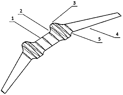
[0024] Present embodiment adopts two symmetrically arranged fuselages 3, from the perspective of plane projection, as figure 1 As shown, the two fuselages 3 are distributed symmetrically and arranged parallel to each other on the same horizontal plane. The straight wing 1 is used to connect two fuselages 3, the two ends of the straight wing 1 are respectively connected to a fuselage 3 through an inner wing-body fusion section 2, and the outer sides of each fuselage 3 are fused through the outer wing body Segment 5 connects an outboard wing 4 .

[0025] Compared with the existing single fuselage layout, the fuselage layout implemented in this implementation adopts twin fuselages and straight wings, which increases the internal space of the two fuselages, so the overall structural layout is more convenient. The overall structural efficiency is higher than the existing single fuselage layout.

[0026] For this embodiment, in order to realize the convenience of processing and m...

Embodiment 2

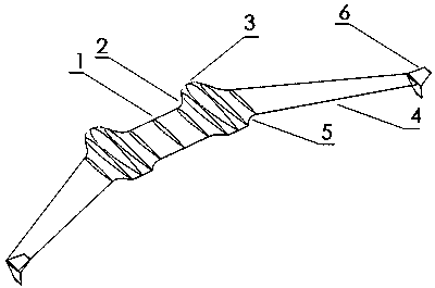
[0034] Such as figure 2 As shown, on the basis of Embodiment 1, a wingtip vertical tail 6 is added to the tip of the outer wing 4, the purpose of which is to increase the heading stability.

[0035] For the layout of the engine in the above two embodiments, the following two different arrangements of built-in and external can be adopted:

[0036] Built-in engine: An engine is respectively arranged in the two fuselages, and the engine is used to realize push-back propulsion.

[0037] External engine:

[0038] The first type is that the external suspension engines on the two fuselages can be arranged above or below the fuselage, and the engines can be used to realize push-back propulsion.

[0039] In the second type, the engine is suspended at the center of the straight wing, which can be above or below the straight wing, and the engine is no longer arranged on the fuselage.

[0040] Above-mentioned engine can adopt jet engine, also can adopt conventional piston or turboshaf...


PUM


Abstract

The invention discloses an air vehicle adopting a large-aspect-ratio double-fuselage flying wing layout. The air vehicle comprises two fuselages which are symmetrically arranged, the two fuselages areconnected into a wing-fuselage integrated entirety through a straight wing, and a wing-fuselage integrated outer side wing is connected to the outer side of each fuselage. According to the air vehicle adopting the large-aspect-ratio double-fuselage flying wing layout, the double-fuselage integrated layout is achieved through the straight wing, the straight wing and the double fuselages form the entirety, the structural strength of the large-aspect-ratio air vehicle is improved, and the structural weight of the large-aspect-ratio air vehicle is lower; the aspect ratio of the whole air vehiclecan be increased, the aerodynamic efficiency of the air vehicle is higher, the flying resistance is lower, and energy consumption is lower; and the area proportion of whole air vehicle lift force canbe increased, that is to say, the area, providing the lift force, of the whole air vehicle surface is larger, the area generating the resistance is smaller, the flying lift-drag ratio is higher, and the flying time is longer.

Description

technical field [0001] The invention relates to the field of aerodynamics, in particular to an aircraft adopting a large-aspect-ratio twin-fuselage flying-wing layout. Background technique [0002] Aircraft is the backbone of modern national defense, and it is also a symbol of the comprehensive strength of a major country such as economic strength, scientific and technological strength, and basic industry. In the complex system engineering of aircraft design, aerodynamic layout design is the forerunner and the most important thing. It is directly related to the layout and design of all subsystems, and is also a key factor for each system to realize its potential. For large-aspect-ratio aircraft, the more common aerodynamic layout schemes include conventional layout, delta wing layout, flying wing layout and wing-body fusion layout. In order to give full play to the aerodynamic efficiency and structural efficiency of the shape layout, these layouts still have a certain poten...

Claims


Application Information

Patent Timeline
IPC IPC(8): B64C39/10B64C3/10B64C3/36B64D27/26
CPCB64C39/10B64C3/10B64C3/36B64D27/40
Inventor 杨小川刘刚毛仲君汪华松叶德章贾涛刘进罗巍魏建烽何炬恒姜久龙徐海航黄平方桂才马跃洪俊武孟德虹孙岩李伟
Owner CALCULATION AERODYNAMICS INST CHINA AERODYNAMICS RES & DEV CENT
Why Eureka
Try Eureka