Life prediction method of IGBT device based on semi-physical simulation platform

A technology of semi-physical simulation and life prediction, which is applied in the fields of instruments, special data processing applications, electrical digital data processing, etc., and can solve the problems of high investment cost, low practicability, and low accuracy

Active Publication Date: 2019-08-20
XIAN YONGDIAN ELECTRIC
View PDF3 Cites 8 Cited by
  • Summary
  • Abstract
  • Description
  • Claims
  • Application Information

AI Technical Summary

Problems solved by technology

[0004] However, there is a certain difference between the IGBT junction and case temperature obtained by using the power consumption and junction temperature simulation software of the module and the real data, and the accuracy is not high
Collect rea

Method used


Image

  • Life prediction method of IGBT device based on semi-physical simulation platform
  • Life prediction method of IGBT device based on semi-physical simulation platform
  • Life prediction method of IGBT device based on semi-physical simulation platform

Examples


Embodiment 1

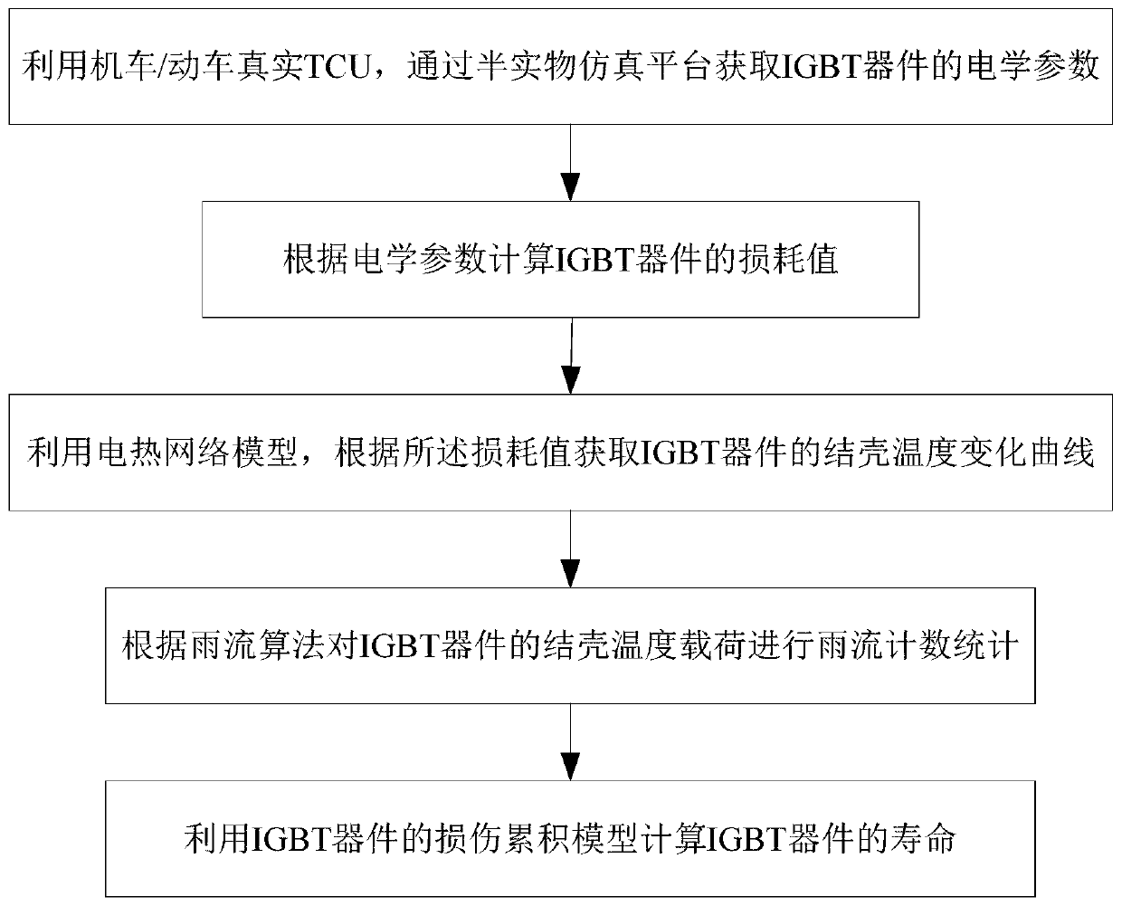
[0081] see figure 1 As shown, the present invention provides a kind of life prediction method of the IGBT device based on hardware-in-the-loop simulation platform, specifically comprises the following steps:

[0082] 1) Use the real TCU of the locomotive / motor car to obtain the electrical parameters of the IGBT device through the semi-physical simulation platform;

[0083] 2) calculating the loss value of the IGBT device according to the electrical parameters;

[0084] 3) using the electrothermal network model to obtain the junction temperature variation curve of the IGBT device according to the loss value;

[0085] 4) Perform rainflow counting statistics on the crust temperature load of the IGBT device according to the rainflow algorithm;

[0086] 5) Use the damage accumulation model of IGBT devices to calculate the lifetime of IGBT devices.

[0087] Further, step 1) uses the real TCU of the locomotive / motor car to obtain the electrical parameters of the IGBT device throug...

Embodiment 2

[0143] On the basis of Example 1, Infineon’s life prediction solution takes into account ΔT j (junction temperature change), ΔT c (Case temperature change) and the effect of device switching frequency on life. The Weibull failure formula is used to calculate the power cycle life / thermal cycle life of the device, and finally the final life prediction value of the device is obtained by integrating the power cycle life and thermal cycle life.

[0144] Taking the new eight-axle locomotive as an example, the half-physical simulation obtains the mission curve Figure 5 As shown, the temperature load change (temperature change amplitude, quantity, and average temperature) after rainflow counting is shown in Figure 6. Figure 6(a) is the change diagram of junction temperature load after rainflow processing, and Figure 6(b) is Shell temperature load change diagram after stream processing:

[0145] Among them, CH1: four-quadrant U-phase upper tube pulse; CH2: four-quadrant Uab voltage...


PUM


Abstract

The invention belongs to the technical field of power electronic devices for rail transit, and particularly relates to an IGBT device service life prediction method based on a semi-physical simulationplatform, which comprises the following steps: obtaining electrical parameters of an IGBT device through the semi-physical simulation platform by using a locomotive/bullet train real TCU; calculatinga loss value of the IGBT device according to the electrical parameters; utilizing an electric heating network model to obtain a crusting temperature change curve of the IGBT device according to the loss value; performing rain current counting statistics on the crusting temperature load of the IGBT device according to a rain current algorithm; and calculating the service life of the IGBT device byusing the damage accumulation model of the IGBT device. According to the service life prediction method, current and voltage changes which are closer to actual working conditions are provided by using the real TCU of the bullet train/locomotive and are equivalent to the accuracy of on-site acquired data, so that a theoretical basis is provided for determining the replacement time of the IGBT device for rail transit and realizing the full-service life cycle management of the IGBT device.

Description

technical field [0001] The invention belongs to the technical field of power electronic devices for rail transit, and relates to a method for predicting the life of an IGBT device, in particular to a method for predicting the life of an IGBT device based on a hardware-in-the-loop simulation platform. Background technique [0002] As a power switching device, an insulated gate bipolar transistor (IGBT) has many advantages such as high current density and low saturation voltage. It is widely used in rail transportation, smart grid, industrial control, electric vehicles and other fields. The working environment of IGBT devices is harsh, such as high current intensity, high voltage level, and high switching frequency during operation, which will easily lead to device fatigue and aging, and bring hidden dangers to the reliability of the device. Through long-term research and work experience, about 55% of the failures are due to the high voltage, current, and switching frequency o...

Claims


Application Information

Patent Timeline
IPC IPC(8): G06F17/50
CPCG06F2119/04G06F30/20
Inventor 叶娜曹琳李萍李碧珊吴晓威
Owner XIAN YONGDIAN ELECTRIC
Why Eureka
Try Eureka