
High-efficiency denitration and plume elimination system for flue gas from sintering machine

A sintering machine and flue gas technology, applied in the separation of dispersed particles, chemical instruments and methods, and filtration of dispersed particles, can solve the problems of shortened service life, large vibration, fixed height, etc., and achieve the goal of reducing fuel consumption and increasing specific surface area Effect

Pending Publication Date: 2019-08-23
无锡市东方环境工程设计研究所
View PDF0 Cites 5 Cited by
  • Summary
  • Abstract
  • Description
  • Claims
  • Application Information

AI Technical Summary

Problems solved by technology

[0003] 1. At present, most high-efficiency denitrification and whitening systems for sintering machine flue gas on the market vibrate greatly during use, which will cause unstable electrical connections within the system's internal electrical components and greatly shorten the service life of the equipment;
[0004] 2. At present, most sintering machine flue gas high-efficiency denitrification and whitening systems on the market can only remove nitrates in the flue gas, and it is not convenient to remove sulfur oxides and smoke in the waste gas;
[0005] 3. At present, most sintering machine flue gas high-efficiency denitrification and whitening systems on the market have a fixed height, which is not convenient for use with sintering machines of different heights

Method used

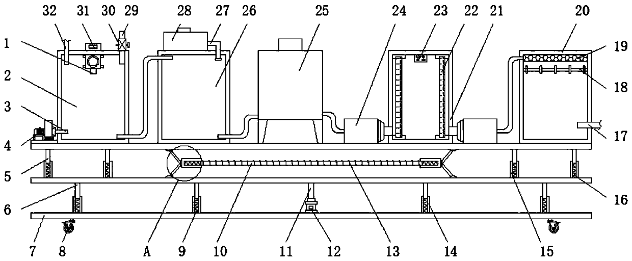
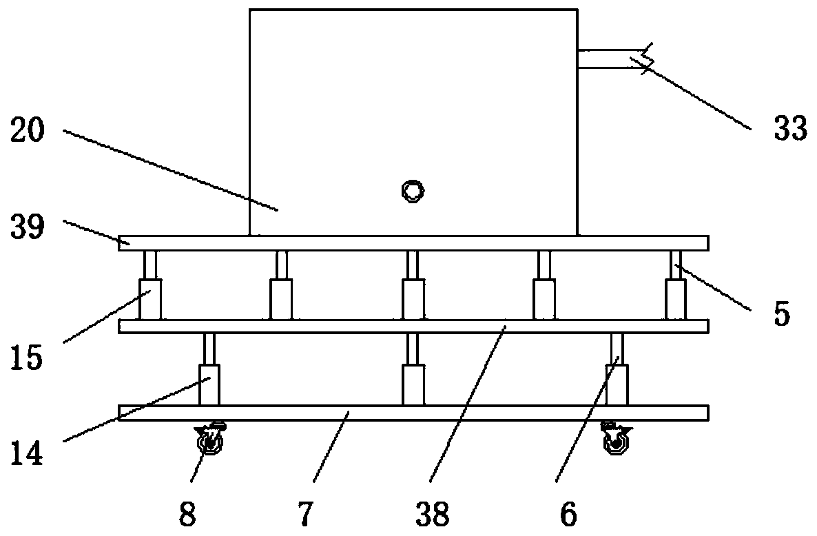
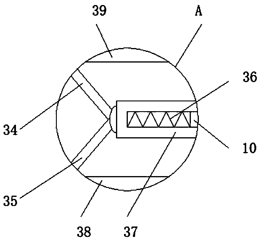

Image

  • High-efficiency denitration and plume elimination system for flue gas from sintering machine
  • High-efficiency denitration and plume elimination system for flue gas from sintering machine
  • High-efficiency denitration and plume elimination system for flue gas from sintering machine

Examples


Embodiment Construction

[0023] The following will clearly and completely describe the technical solutions in the embodiments of the present invention with reference to the accompanying drawings in the embodiments of the present invention. Obviously, the described embodiments are only some, not all, embodiments of the present invention. Based on the embodiments of the present invention, all other embodiments obtained by persons of ordinary skill in the art without making creative efforts belong to the protection scope of the present invention.

[0024] see Figure 1-3, an embodiment provided by the present invention: a high-efficiency denitrification and whitening system for flue gas of a sintering machine, including a first platform 7 and a third platform 39, a cylinder 12 is installed on the top of the first platform 7, The model of the cylinder 12 can be a J64RT2UNIVER telescopic cylinder, the two ends of the bottom end of the first bearing plate 7 are equipped with universal wheels 8, and two sets...


PUM


Abstract

The invention discloses a high-efficiency denitration and plume elimination system for flue gas from a sintering machine. The system comprises a first bearing plate and a third bearing plate; and an air cylinder is installed at the top end of the first bearing plate, a second bearing plate is installed at the top end of a hydraulic rod, a connecting rod passing through a second sleeve cylinder isinstalled in the second sleeve cylinder through a third spring, an air blower is horizontally installed at one end of the top end of the third bearing plate, an air outlet pipe passing through a firstreaction box is installed at the output end of the air blower, a bag-type dust collector is installed on the top end of one part, located at one side, far away from the first reaction box, of a fourth reaction box, of the third bearing plate, and a second reaction box is installed at the top end of one part, far away from the bag-type dust collector, of a third reaction box, of the third bearingplate. According to the high-efficiency denitration and plume elimination system for the flue gas from the sintering machine provided by the invention, the third bearing plate transfers impact force generated by vibration to the first connecting rod and a fourth connecting rod, and the impact force generated by the vibration is eliminated by the third spring, a fourth spring and a second spring, so that the cushion shock absorption is facilitated.

Description

technical field [0001] The invention relates to the technical field of denitrification equipment, in particular to a high-efficiency denitrification and whitening system for flue gas of a sintering machine. Background technique [0002] The waste gas emitted during the use of the sintering machine contains a large amount of nitrate oxides, so in order to meet my country's waste gas emission standards, it is necessary to treat the nitrate oxides in the waste gas. [0003] 1. At present, most high-efficiency denitrification and whitening systems for sintering machine flue gas on the market vibrate greatly during use, which will cause unstable electrical connections within the system's internal electrical components and greatly shorten the service life of the equipment; [0004] 2. At present, most sintering machine flue gas high-efficiency denitrification and whitening systems on the market can only remove nitrates in the flue gas, and it is not convenient to remove sulfur oxi...

Claims


Application Information

Patent Timeline
IPC IPC(8): B01D53/90B01D53/83B01D53/50B01D46/02B01D53/56
CPCB01D46/023B01D53/50B01D53/83B01D53/8625B01D53/90
Inventor 郑岩仲华
Owner 无锡市东方环境工程设计研究所
Learn More