Novel shaft end sealing device

A new type of shaft end sealing technology, applied in the direction of engine sealing, transmission parts, engine components, etc., can solve the problems of high internal pressure of the reducer, leakage of lubricating oil, etc., to achieve simple structure, improved sealing performance, small size Effect

Inactive Publication Date: 2019-08-23
DALIAN JIAOTONG UNIVERSITY
View PDF5 Cites 0 Cited by
  • Summary
  • Abstract
  • Description
  • Claims
  • Application Information

AI Technical Summary

Problems solved by technology

[0003] We have designed a new type of shaft end sealing device, which combines the impeller group and the labyrinth seal. Through the structure of the impeller group and the synchronous rotation of the transmission shaft, different pressure areas with high pressure in the middle and low pressure on both sides are formed inside the bearing end cover to solve the problem caused by high speed. Lubricating oil leakage caused by the internal pressure of the reducer being higher than the external pressure due to the action of the piston wind when the running EMU train passes through the tunnel

Method used


Image

  • Novel shaft end sealing device
  • Novel shaft end sealing device
  • Novel shaft end sealing device

Examples


Embodiment Construction

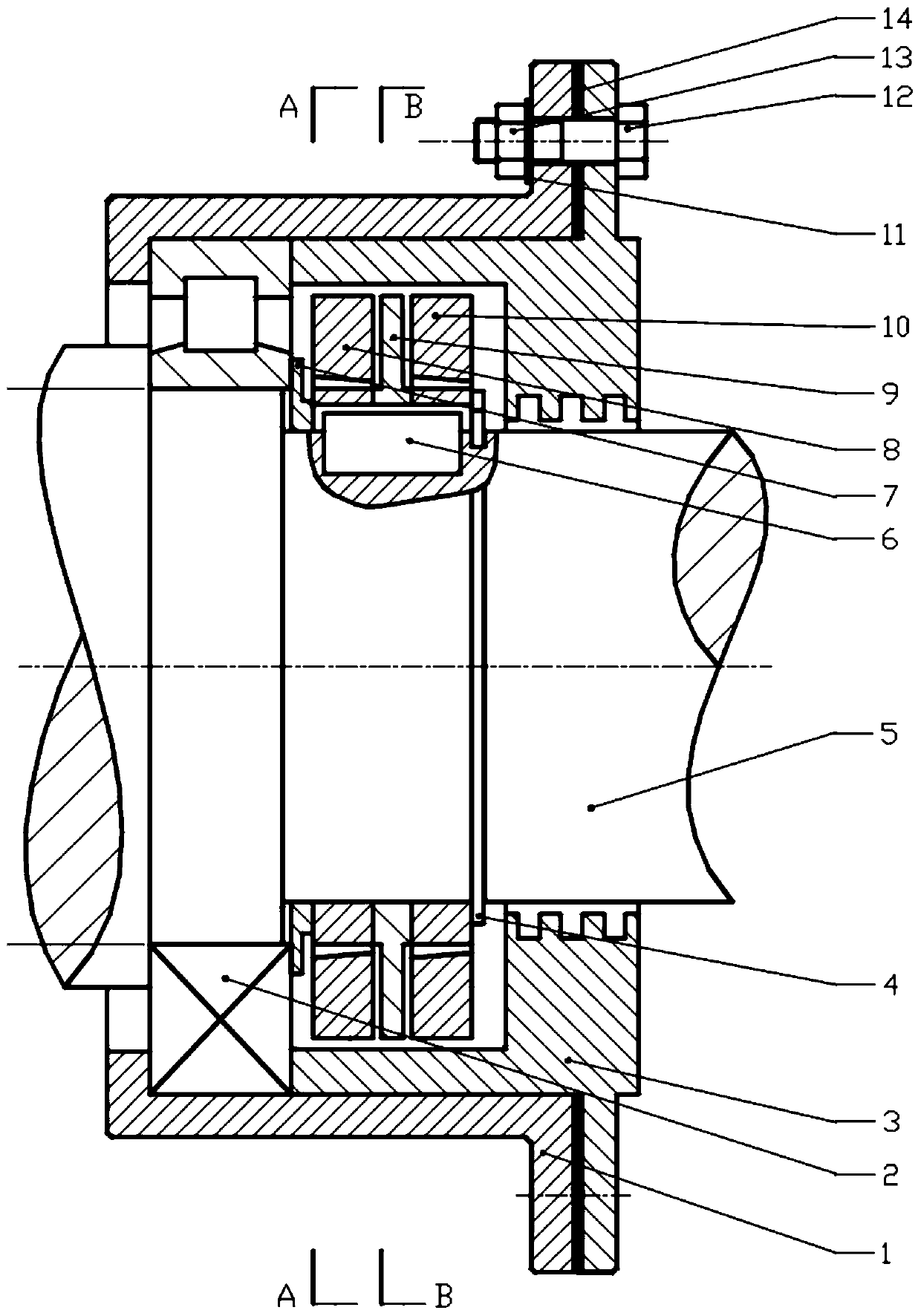
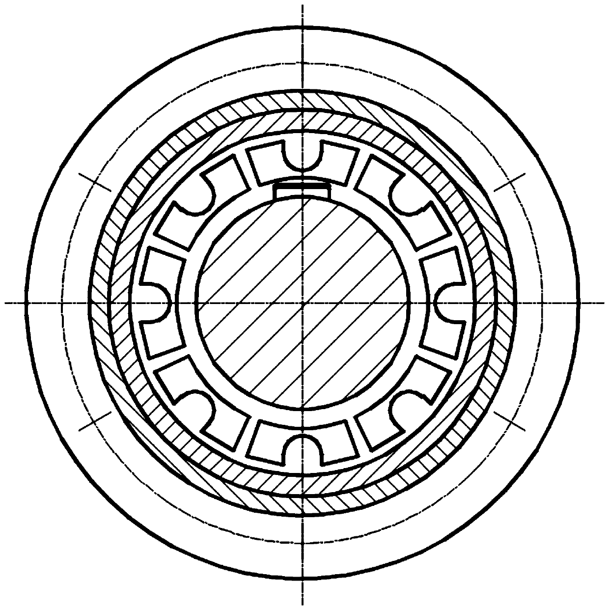
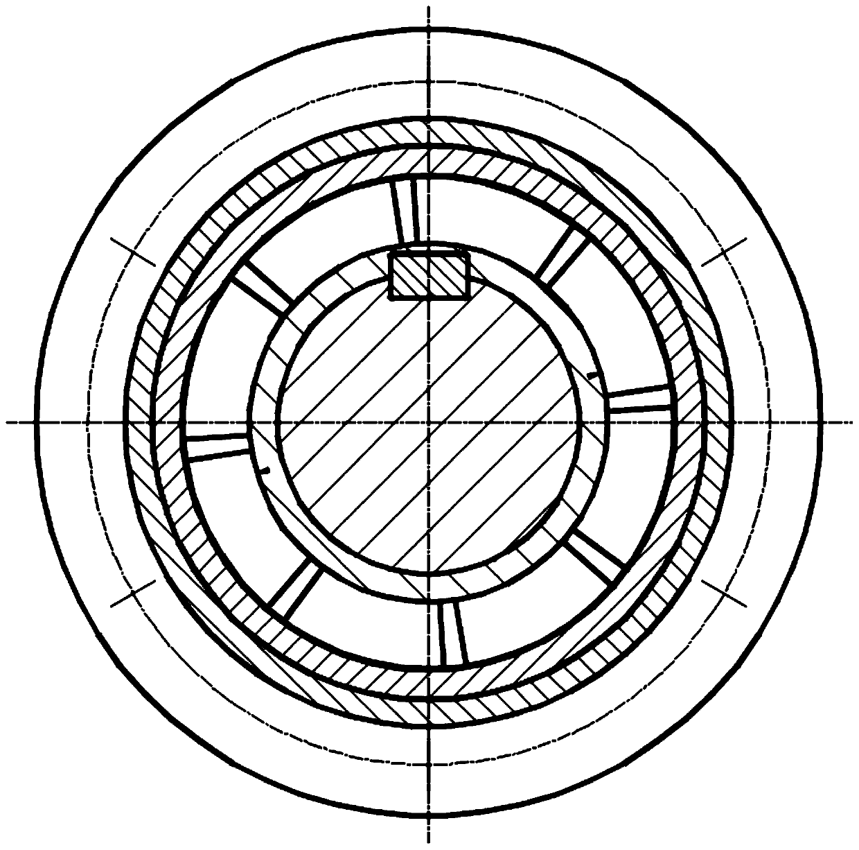
[0023] Such as figure 1 , figure 2 , image 3 , Figure 4 , Figure 5 , Figure 6 , Figure 7 , Figure 8 , Figure 9 A new type of shaft end sealing device is shown, including box body 1, bearing 2, bearing end cover 3, shaft circlip 4, transmission shaft 5, flat key 6, sleeve 7, impeller I 8, impeller II 9, Impeller III 10, elastic gasket 11, hexagonal bolt 12, hexagonal nut 13, asbestos pad 14, characterized in that the transmission shaft 5 is equipped with a bearing 2, the inner ring of the bearing 2 is axially fixed by the sleeve 7, and the inner ring of the bearing 2 is fixed by the elastic Gasket 11, hexagonal bolt 12, hexagonal nut 13 are fixed on the shaft end cover 3 on the box body 1 to axially fix the outer ring of the bearing 2; The impeller Ⅰ8, impeller Ⅱ9 and impeller Ⅲ10 are also installed in sequence, the axial axis is fixed by the elastic retaining ring 4, and the circumferential direction is connected by the flat key 6, so that the three impellers r...


PUM


Abstract

The invention discloses a novel shaft end sealing device. A bearing is mounted on a transmission shaft; a bearing inner ring is fixedly arranged close to a sleeve; a bearing outer ring is fixedly arranged close to a bearing end cover; an impeller I, an impeller II and an impeller III are sequentially mounted on the transmission shaft, fixing in the axial direction is achieved through an elastic retainer ring, and connection in the peripheral direction is achieved through a flat key, so that the three impellers synchronously rotate along with the transmission shaft; a pressure area with high pressure in middle and low pressure at the two sides is formed inside the bearing end cover, so that the problem that lubricating oil leakage is caused as internal pressure intensity of a speed reduceris greater than external pressure intensity of the speed reducer as a result of action of piston wind while the multiple unit train in high-speed operation passes through a tunnel is solved; eight tapered impeller baffle blocks are uniformly distributed and welded inside impeller rings, so that narrow seams with large and small ends are formed, and the narrow seams with large ends are mounted at abearing end; the impeller III and the impeller I are the same in structure, and are mounted in the same direction; and eight narrow seams are uniformly formed in the impeller II. The structure dimension value range of the impellers is given. The novel shaft end sealing device solves the speed reducer oil leakage problem while the multiple unit train passes through the tunnel, and has the advantages of being simple in structure, small in size, high in reliability, and the like.

Description

technical field [0001] The technology of the invention mainly relates to a shaft end sealing structure, which is especially suitable for train speed reducers of EMUs, and belongs to the technical field of mechanical equipment sealing. Background technique [0002] In recent years, with the rapid development of my country's rail transit industry, EMU trains "Harmony" and "Fuxing" are a very representative business card in China. In response to faster running speed and more complex and changeable The terrain also puts forward higher requirements for the reducer in the power part of the EMU train. [0003] We have designed a new type of shaft end sealing device, which combines the impeller group and the labyrinth seal. Through the structure of the impeller group and the synchronous rotation of the transmission shaft, different pressure areas with high pressure in the middle and low pressure on both sides are formed inside the bearing end cover to solve the problem caused by high...

Claims


Application Information

Patent Timeline
Patent Type & Authority Applications(China)
IPC IPC(8): F16H57/029F16J15/40F16J15/447
CPCF16H57/029F16J15/406F16J15/447
Inventor 李宝良林佳旭
Owner DALIAN JIAOTONG UNIVERSITY
Why Eureka
Try Eureka