Laser raman and laser fluorescence-based water surface oil film thickness measurement method

A technology of oil film on water surface and measurement method, which is applied in the direction of measuring device, optical device, instrument, etc., can solve the problems of weakening of water Raman scattering intensity, inability to measure oil film, and limited oil film measurement range

Active Publication Date: 2019-08-23
HARBIN INST OF TECH AT WEIHAI +1
View PDF15 Cites 3 Cited by
  • Summary
  • Abstract
  • Description
  • Claims
  • Application Information

AI Technical Summary

Problems solved by technology

Among them, the fluorescence method is to directly detect the fluorescence intensity of the oil film, and calculate the thickness of the oil film through the fluorescence intensity. Since the fluorescence intensity detected at different distances and different angles is different, this method is only applicable to the measurement of the thickness of the oil film on the water surface at a fixed distance; the Raman attenuation method is to detect water The light intensity at the Raman scattering wavelength is the light intensity at the Raman scattering wavelength. When the water surface is not covered by oil film, the water stimulated Raman scattering is the strongest. As the oil film thickness increases, the water Raman scattering intensity weakens. The oil film thickness is calculated by the degree of reduction of water Raman scattering. This method has no water Raman scattering signal when the oil film is thick, so this method is suitable for measuring the thickness of thin oil film, and the oil film measurement range is limited
The traditional fluorescence Raman ratio method also needs to measure the water Raman signal after the oil film is covered, so it cannot measure the thicker oil film

Method used


Image

  • Laser raman and laser fluorescence-based water surface oil film thickness measurement method
  • Laser raman and laser fluorescence-based water surface oil film thickness measurement method
  • Laser raman and laser fluorescence-based water surface oil film thickness measurement method

Examples


Embodiment Construction

[0014] The specific embodiments of the present invention will be further described below in conjunction with the accompanying drawings.

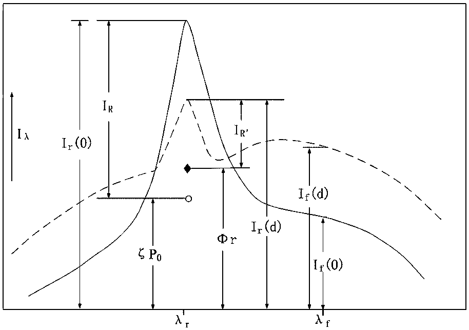
[0015] When the laser spectrum oil film thickness detection system (or other detection equipment in the prior art) emits laser light to irradiate the surface of the oil film on the water surface, while exciting the oil substance to radiate fluorescence, the water will generate Raman scattered light, that is to say, it will The oil film fluorescence signal (referred to as oil fluorescence) and the water Raman scattering signal (referred to as water Raman) are excited. figure 1 are the laser Raman and laser fluorescence spectrum models and their parameters when there is oil film and no oil film on the water surface, where the dotted line represents the spectral curve when there is oil film, and the solid line represents the spectral curve when there is no oil film.

[0016] figure 1 The meanings of the parameters are as follows: P 0 : emitte...


PUM


Abstract

The invention provides a laser raman and laser fluorescence-based water surface oil film thickness measurement method. The method comprises the following steps that a total attenuation coefficient A is measured in advance; a saturation fluorescence constant C is measured in advance, wherein the value is equal to the ratio of the intensity of an oil saturation fluorescence signal at the oil film covering part at the same distance from the detection system to the surface of the water film to the intensity of a water raman signal after subtracting the fluorescence background in the position without oil film; in a to-be-tested water area, the water raman signal intensity IR after ignoring the fluorescence background in the position without the oil film at the same distance from the water surface to the detection system, and the fluorescent signal intensity If(d) in the position with the wavelength of lambda f at the oil film covering position are measured onsite; and according to a formula, the thickness of the oil film in the water area to be measured is calculated, wherein d is the thickness of the oil film, A is the total attenuation coefficient, and C is the saturation fluorescenceconstant; the thickness of the water surface oil film can be obtained at different distances, the measurement range of the thickness of the oil film is relatively wide, and great significance is achieved for the practical application of the non-contact water surface oil film thickness measurement technology.

Description

technical field [0001] The invention relates to the field of measuring the thickness of the oil film on the water surface, in particular to a method for measuring the thickness of the oil film on the water surface based on laser Raman and laser fluorescence. Background technique [0002] With the continuous improvement of the development speed of marine resources in recent years, the exploitation, transportation and use of a large amount of oil have made the marine oil pollution more and more serious, among which the oil spill at sea is one of the most serious pollution causes. After a marine oil spill accident, obtaining accurate information on the type and thickness of oil spilled in time is of great guiding significance for formulating rapid and effective control measures. [0003] As an active optical detection technology, laser spectroscopy technology, when the laser is incident on the water surface covered by oil film, while exciting the oil substance to radiate fluore...

Claims


Application Information

Patent Timeline
Patent Type & Authority Applications(China)
IPC IPC(8): G01B11/06
CPCG01B11/06
Inventor 田兆硕尹松林张延超毕宗杰王玲刘文军付石友
Owner HARBIN INST OF TECH AT WEIHAI
Why Eureka
Try Eureka