
Radar beam forming method based on power iteration generalized Rayleigh quotient algorithm

A radar beam and iterative technology, which is applied in the field of communication and radar beamforming, can solve the problems of inability to form real-time radar beams, large amount of calculation for solving the sample covariance matrix, and inability to effectively suppress radar beam interference and noise, etc., so as to facilitate rapid implementation , reduce computational complexity, and suppress interference and noise

Active Publication Date: 2019-08-23
XIDIAN UNIV
View PDF4 Cites 4 Cited by
  • Summary
  • Abstract
  • Description
  • Claims
  • Application Information

AI Technical Summary

Problems solved by technology

The shortcomings of this method are: this method converts the original non-convex problem into a convex second-order cone programming (SOCP) under the worst-case performance-optimized (WCPO) criterion, and uses the traditional efficient interior point method solve
The shortcomings of this method are: firstly, the method utilizes the linear minimum mean square error (LMMSE) and minimum variance distortion-free response (MVDR) criteria, and it is difficult to effectively resist large steering vectors when diagonally loading the sample covariance matrix The mismatch makes the system unable to effectively suppress the interference and noise in the process of radar beamforming. Secondly, when the number of samples is large, the amount of calculation to solve the sample covariance matrix is ​​large, and the radar beamforming cannot be performed in real time.

Method used


Image

  • Radar beam forming method based on power iteration generalized Rayleigh quotient algorithm
  • Radar beam forming method based on power iteration generalized Rayleigh quotient algorithm
  • Radar beam forming method based on power iteration generalized Rayleigh quotient algorithm

Examples


Embodiment Construction

[0028] The present invention will be further described below in conjunction with the accompanying drawings.

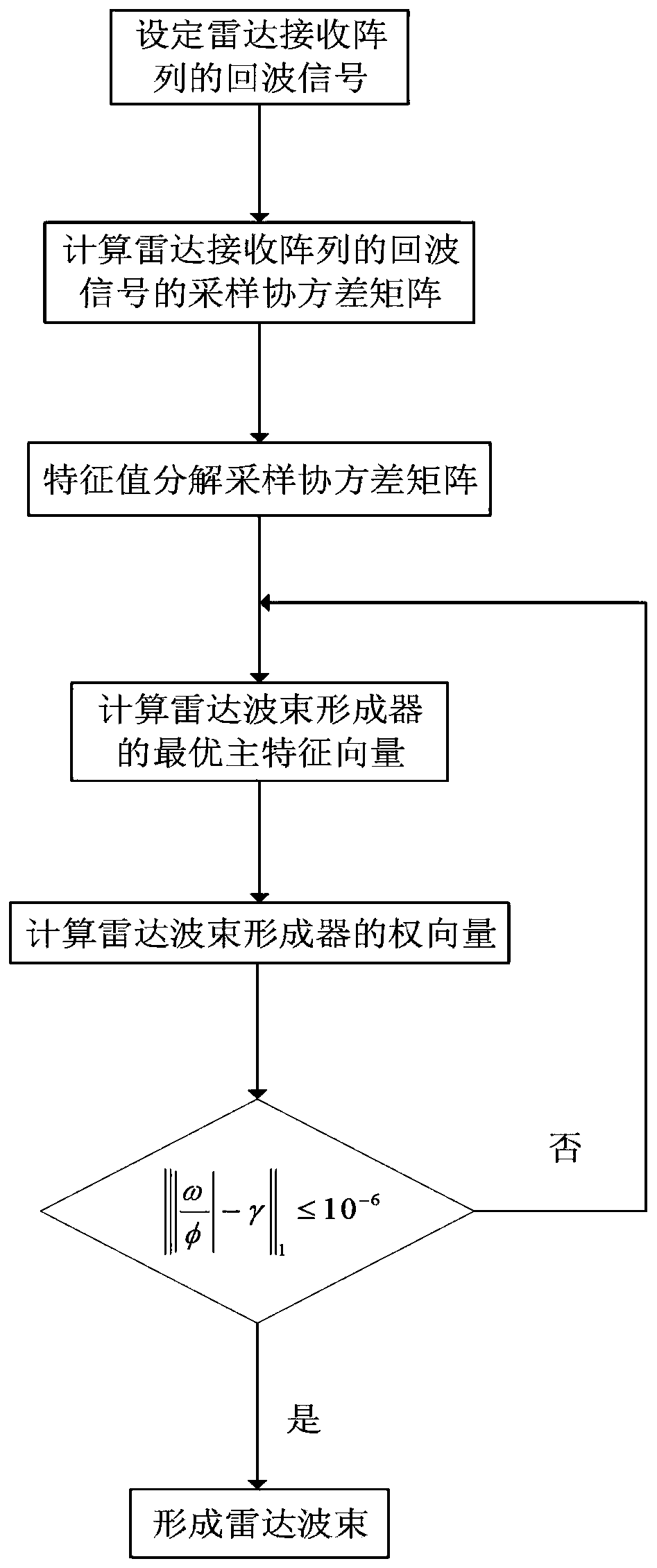
[0029] refer to figure 1 , to further describe the specific implementation steps of the present invention.

[0030] Step 1. Set the echo signal of the radar receiving array including the steering vector.

[0031] The expression of the echo signal of the radar receiving array including the steering vector is set as follows:

[0032]

[0033] Among them, x represents the echo signal received by the radar receiving array, β(θ 0 ) means that the radar detects θ 0 The amplitude of the echo signal reflected back to the radar receiving array by the ground object in azimuth, a(θ 0 ) means that the radar detects θ 0 The steering vector of the echo signal reflected by the ground objects at the azimuth angle to the radar receiving array, P represents the total number of interference signals received by the radar receiving array from different azimuth angles, ∑ represents ...


PUM


Abstract

A radar beam forming method based on the power iteration generalized Rayleigh quotient algorithm is implemented through the following steps: 1. setting echo signals of a radar receiving array; 2. calculating a sampling covariance matrix; 3. carrying out eigenvalue decomposition on the sampling covariance matrix; 4. calculating the optimal principal eigenvector of a radar beam former; 5. calculating a weight vector of the radar beam former; 6. judging whether a ratio between the weight vector of the radar beam former during the current iteration and the weight vector of the radar beam former during the previous iteration satisfies a designated condition or not, obtaining the optimal weight of the radar beam former and carrying out Step 7 if the ratio satisfies the designated condition, andcarrying out Step 4 if the ratio does not satisfy the designated condition; and 7. forming radar beams. The method provided by the invention has the advantages that the calculation amount and the calculation complexity can be greatly reduced, so that quick achievement of radar beam forming can be facilitated; and interferences and noises can be effectively inhibited, so that the method can be usedfor the radar beam forming under the condition of steering vector mismatch during radar signal processing.

Description

technical field [0001] The invention belongs to the technical field of communication, and further relates to a radar beam forming method based on a power iteration generalized Rayleigh quotient algorithm in the technical field of radar beam forming. The invention can be used for radar beam forming under the condition of steering vector mismatch in the radar signal processing process. Background technique [0002] Adaptive beamforming is mainly to enhance or suppress the incoming signals at different guiding positions in space, so as to improve the output signal-to-interference-noise ratio (SINR) of the system. The Capon beamformer belongs to the adaptive beamformer that adaptively adjusts the weight vector by minimizing the output power while linearly constraining the target signal, a criterion also known as the minimum variance distortion-free response (MVDR) criterion . When the array steering vector is determined and known, the minimum variance distortion free response ...

Claims


Application Information

Patent Timeline
Patent Type & Authority Applications(China)
IPC IPC(8): G01S7/41
CPCG01S7/418
Inventor 冯大政任晓丽虞泓波梁雪彦
Owner XIDIAN UNIV
Learn More