Battery pack, vehicle and energy storage device

A battery pack and battery placement technology, applied in vehicle energy storage, electric power devices, battery/fuel cell control devices, etc., can solve problems such as adverse effects on battery pack quality, reduced reliability, increased manpower, material resources and other costs

Active Publication Date: 2019-08-23
BYD CO LTD
View PDF5 Cites 13 Cited by
  • Summary
  • Abstract
  • Description
  • Claims
  • Application Information

AI Technical Summary

Problems solved by technology

[0007] As the user's requirements for the battery life of the electric vehicle gradually increase, and in the case of limited space at the bottom of the vehicle body, the battery pack provided by the above-mentioned related technical embodiment, the end plate and the side plate of the battery module 400, and the internal parts of the battery pack Connection and installation methods, etc., all reduce the utilization rate of the internal space of the battery pack; as a result, the ratio of the volume of the single cells in the battery pack to the volume of the battery pack is too low, and its energy density cannot meet the above-mentioned deman

Method used


Image

  • Battery pack, vehicle and energy storage device
  • Battery pack, vehicle and energy storage device
  • Battery pack, vehicle and energy storage device

Examples


Example Embodiment

[0302] Example 1

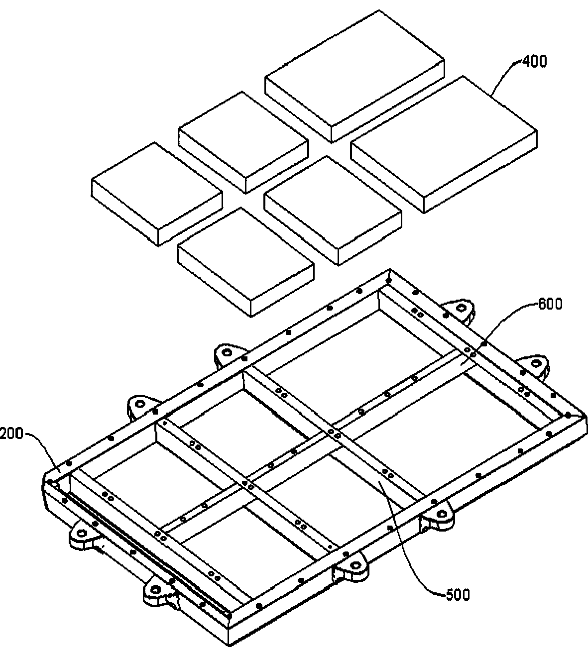
[0303] According to the battery pack 200 of the embodiment of the present application, such as Figure 21As shown, the length direction of the single battery 100 is arranged along the width direction of the battery pack 200, a plurality of single cells 100 are arranged along the length direction of the battery pack 200, and in the width direction of the battery pack 200, the battery pack housing accommodates a single The battery 100 , the single battery 100 extends from one side of the battery pack case to the other side in the width direction of the battery pack 200 . A first separator 700 is arranged inside the battery pack casing, and the second separator 800 is not provided. The first separator 700 extends along the width direction of the battery pack 200 , and a plurality of single cells 100 are arranged along the length direction of the battery pack 200 to form For the battery array 400 , the first separator 700 divides the battery array 400 into two ...

Example Embodiment

[0304] Example 2

[0305] According to the battery pack 200 of the embodiment of the present application, such as Figure 23 As shown, the length direction of the single battery 100 is arranged along the width direction of the battery pack 200, a plurality of single cells 100 are arranged along the length direction of the battery pack 200, and in the width direction of the battery pack 200, the battery pack housing accommodates a single The battery 100 , the single battery 100 extends from one side of the battery pack case to the other side in the width direction of the battery pack 200 . The first separator 700 and the second separator 800 are not provided in the battery pack casing. The first side beams 201 and the second side beams 202 of the battery pack casing located on both sides of the battery pack 200 in the width direction provide support for the single battery 100 , and the third side beams 203 of the battery pack casing located at both ends of the battery pack 200...

Example Embodiment

[0310] Example 3

[0311] According to the battery pack 200 of the embodiment of the present application, such as Figure 20 As shown, the length direction of the single cells 100 is arranged along the length direction of the battery pack 200, a plurality of single cells 100 are arranged along the width direction of the battery pack 200, and in the length direction of the battery pack 200, the battery pack housing accommodates a single The battery 100 , the single battery 100 extends from one side of the battery pack case to the other side in the length direction of the battery pack 200 . A second separator 800 is arranged inside the battery pack housing without the beam 500. The second separator 800 extends along the length direction of the battery pack 200, and a plurality of single cells 100 are arranged along the width direction of the battery pack 200 to form a battery array 400. , the second separator 800 divides the battery array 400 into two parts along the width dire...


PUM

PropertyMeasurementUnit
Lengthaaaaaaaaaa
Lengthaaaaaaaaaa
Widthaaaaaaaaaa

Abstract

The invention discloses a battery pack, a vehicle and an energy storage device. The battery pack comprises a battery array and a support member, wherein the battery array includes a plurality of single batteries, the single batteries have a first size, and the first size is the maximum value of the distance between two parallel planes virtually clamping the single battery; at least one single battery satisfies the following conditions: the first size is greater than or equal to 600mm and less than or equal to 2500mm, and the single battery is supported on the support member; the normal direction of the two parallel planes corresponding to the first size is the Q-direction, the battery pack is internally provided with a battery placement area, the battery array is located in the battery placement area, and the single battery extends from one side of the battery placement area to the other side of the battery placement area in the Q-direction. According to the battery pack of the invention, the plurality of long single batteries form the battery pack, so that the battery capacity of the battery pack is improved. Meanwhile, the first size within the specific range is adopted, and thusthe space utilization ratio of the battery pack can be improved.

Description

[0001] Cross References to Related Applications [0002] This application claims the priority of the Chinese patent application numbers "201910021244.0", "201910020967.9", "201910021246.X", "201910021248.9", "201910021247.4" and "201910020925.5" submitted by BYD Co., Ltd. on January 9, 2019. The entire contents are incorporated by reference in this application. technical field [0003] The present application belongs to the technical field of vehicle manufacturing, and in particular, relates to a battery pack, a vehicle with the battery pack, and an energy storage device with the battery pack. Background technique [0004] In the related art, such as battery packs used in electric vehicles, mainly include a battery pack and a plurality of battery modules installed in the battery pack, wherein each battery module is assembled from a plurality of single cells. [0005] Specifically, such as figure 1 As shown, the battery pack includes a battery pack casing, and multiple beam...

Claims


Application Information

Patent Timeline
IPC IPC(8): H01M2/10H01M10/613H01M10/625H01M10/6554H01M10/6556H01M10/6568B60L50/64
CPCH01M10/613H01M10/625H01M10/6554H01M10/6556H01M10/6568B60K1/04B60K2001/0438H01M50/249H01M2220/20H01M50/131H01M50/209H01M50/103H01M50/367H01M10/6567H01M10/6569H01M50/119Y02E60/10H01M50/233H01M50/224H01M50/358H01M50/383B60K2001/0405B60L50/64B60L50/66H01M50/244H01M50/531H01M50/3425H01M50/35H01M50/342H01M50/317H01M10/052H01M10/647H01M10/6551B60L58/26H01M50/543H01M50/271H01M10/425H01M2010/4271
Inventor 王传福何龙孙华军王信月朱燕
Owner BYD CO LTD
Why Eureka
Try Eureka