
A double row quenching method

A quenching machine and header technology, applied in the direction of quenching device, furnace, furnace type, etc., to ensure the uniformity of water spray, solve the phenomenon of split ends, and ensure the uniformity of quenching width

Active Publication Date: 2021-05-11
NANJING IRON & STEEL CO LTD
View PDF4 Cites 0 Cited by
  • Summary
  • Abstract
  • Description
  • Claims
  • Application Information

AI Technical Summary

Problems solved by technology

[0006] Technical effect: the present invention changes the second group of slit nozzles of the quenching machine from the original sub-chamber water spraying to the through-cavity water spraying, and designs the damping structure inside the header so that the water flow is evenly sprayed out after gyrating, thereby solving the problem of Solved the problem of water cooling uniformity of quenching machine

Method used


Image

  • A double row quenching method
  • A double row quenching method
  • A double row quenching method

Examples


Embodiment Construction

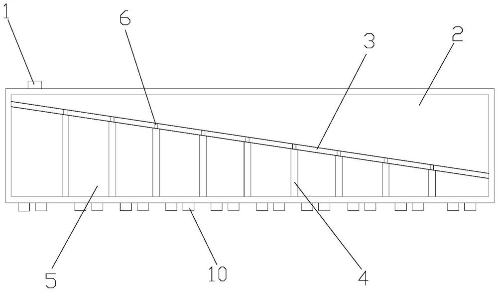
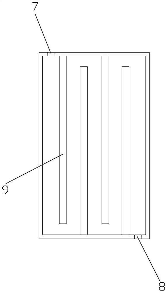
[0031] A double-row quenching method provided in this embodiment has a structure such as Figure 1-2 As shown, the second group of slit nozzles 10 of the quenching machine is changed from the sub-cavity water spray to the through-chamber water spray, the width is set to 4700mm, and the gap opening accuracy in the width direction is 2±0.2mm.

[0032] The header is made of 310S heat-resistant stainless steel, and a damping structure is set in the header to make the water flow evenly swirl and then spray out. One end of the header is provided with a water inlet 1, and the header is provided with a partition plate 3 that divides it into a diversion chamber 2 and a water spray chamber up and down. One end on the same side is higher than the other. The water spray chamber is provided with several damping deflectors 4 evenly distributed along the length direction of the header. The damping deflectors 4 are vertically arranged and hollow inside, and divide the water spray chamber int...


PUM


Abstract

The invention discloses a double-row quenching method, which relates to the field of metallurgical roller quenching machine equipment. The second group of gap nozzles of the quenching machine are changed from a sub-chamber water spray to a through-chamber water spray. The damping structure makes the water flow evenly swirled and sprayed out. The invention changes the second group of slit nozzles of the quenching machine from the original sub-cavity water spraying to the through-cavity water spraying, and makes a damping structure design inside the header, so that the water flow can be evenly sprayed after gyrating, thereby solving the problem of quenching machine Water cooling uniformity problem.

Description

technical field [0001] The invention relates to the field of metallurgical roller quenching machine equipment, in particular to a double-row quenching method. Background technique [0002] The existing roller quenching machine adopts sub-chamber water spraying. The advantage of sub-chamber water spraying is that the opening mode of the nozzle in the width direction can be flexibly adjusted according to the width of the steel plate. When the width is ≤ 3500mm, the side chamber nozzle can not be opened to save water. the goal of. However, when the width of the steel plate is greater than 3500mm, it is necessary to open the side cavity nozzle. Since there is an isolation device at the junction of the side cavity nozzle and the middle nozzle, the nozzle at this point is prone to splitting, resulting in poor hardenability of the steel plate here, which affects the steel plate. Overall uniformity in the width direction. Contents of the invention [0003] In order to solve the ...

Claims


Application Information

Patent Timeline
Patent Type & Authority Patents(China)
IPC IPC(8): C21D1/667C21D9/00
CPCC21D1/667C21D9/0062C21D9/0081
Inventor 王思聪廖仕军顾小阳
Owner NANJING IRON & STEEL CO LTD
Learn More