
Urban catchment potential area identification method

An identification method and potential technology, applied in structured data retrieval, instrumentation, climate change adaptation, etc., can solve the problems of complex division of water catchment potential areas, easy to generate errors, low efficiency, etc., and achieve the goal of improving scientificity and work efficiency Effect

Pending Publication Date: 2019-08-27
SOUTHEAST UNIV
View PDF2 Cites 6 Cited by
  • Summary
  • Abstract
  • Description
  • Claims
  • Application Information

AI Technical Summary

Problems solved by technology

[0002] In the process of sponge city planning and design, the determination of the storage scale of the sponge system is one of the key steps to determine whether the design is rational or not, and it involves the division of sub-catchment potential areas, the determination of design rainfall, and the sub-catchment potential. The water volume calculation and other steps in the urban built environment are quite different from those in the natural environment, and the division of the catchment potential area is also more complicated. Relying on the two-dimensional topographic map to divide the water line under complex urban conditions Operations such as extraction and catchment division have low efficiency and are prone to errors.
[0003] On the other hand, the division of existing urban water catchment areas mainly provides the basis and reference for the design of urban water supply and drainage pipe network systems. The division of water districts is the goal, which has limited effect on the planning and design of sponge cities

Method used


Image

  • Urban catchment potential area identification method

Examples

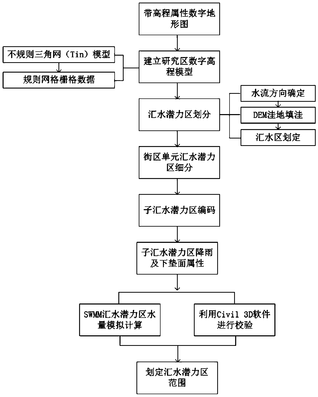

Embodiment Construction

[0024] Below, the present invention will be described in further detail in conjunction with the accompanying drawings.

[0025] Such as figure 1 As shown, aiming at the division of water catchment potential areas in sponge city planning, a method for identifying urban water catchment potential areas is provided, including the following steps:

[0026] (1) Obtain the terrain vector graphic data with elevation attributes of the project area through the design entrusting party or the national surveying, mapping and planning management department. Terrain vector graphic data with elevation attributes can be in DWG format or Shapefile file format. DWG format is a special binary file format used to store two-dimensional and three-dimensional design data and metadata; Shapefile file is a description of spatial data geometry and attributes A format of the characteristic non-topological entity vector data structure, developed by ESRI (Environmental Systems Research Institute, US Envir...


PUM


Abstract

The invention discloses an urban catchment potential area identification method. The method comprises the steps of firstly establishing a digital elevation model of an area where a project is located,and using a hydrological tool for dividing catchment potential areas on the basis of the digital elevation model; counting the area of the water catchment potential areas and encoding the water catchment potential areas; classifying the underlying surfaces of the water catchment potential areas, simulating water catchment in different rainfall recurrence periods by applying an SWMM urban rainfallflood management model, estimating the water amount of each water catchment potential area, identifying water catchment ranges of the water catchment potential areas in the different rainfall recurrence periods, and carrying out verification by combining Civil3D software at the same time. The method takes the dynamic balance of water collection and water utilization of an urban sponge system as aguide, takes a block as a unit to divide urban catchment potential areas, extracts the site hydrological characteristics by constructing a site three-dimensional model, and calculates and verifies the site runoff and confluence conditions by utilizing a rain flood management model and Civil3D software. According to the present invention, an auxiliary tool is provided for the sponge city planningand designing, and the scientificity and the working efficiency of the sponge city planning and designing are improved.

Description

technical field [0001] The invention belongs to the field of sponge city planning and construction, and in particular relates to a method for identifying urban catchment potential areas. Background technique [0002] In the process of sponge city planning and design, the determination of the storage scale of the sponge system is one of the key steps to determine whether the design is rational or not, and it involves the division of sub-catchment potential areas, the determination of design rainfall, and the sub-catchment potential. The water volume calculation and other steps in the urban built environment are quite different from those in the natural environment, and the division of the catchment potential area is also more complicated. Relying on the two-dimensional topographic map to divide the water line under complex urban conditions Operations such as extraction and catchment division are inefficient and prone to errors. [0003] On the other hand, the division of exi...

Claims


Application Information

Patent Timeline
Patent Type & Authority Applications(China)
IPC IPC(8): G06F17/50G06F16/29G06Q50/26
CPCG06F16/29G06Q50/26G06F30/13Y02A10/40
Inventor 成玉宁谢明坤
Owner SOUTHEAST UNIV
Learn More