
Soil beating mechanism and soil remediation system

A soil and beating bucket technology, applied in the field of soil remediation, can solve the problems of stirring blade damage, processing chain extension costs, etc., and achieve the effect of promoting dissolution and facilitating centralized processing

Inactive Publication Date: 2019-08-30
周慧
View PDF5 Cites 0 Cited by
  • Summary
  • Abstract
  • Description
  • Claims
  • Application Information

AI Technical Summary

Problems solved by technology

[0004] In the prior art, the mixing of soil and water is realized by means of stirring, but in actual application, because stones and pebbles in the soil will cause damage to the mixing blade, it is necessary to mix the soil and water before mixing the soil and water Preliminary screening of soils, resulting in extended processing chains and increased costs

Method used


Image

  • Soil beating mechanism and soil remediation system
  • Soil beating mechanism and soil remediation system
  • Soil beating mechanism and soil remediation system

Examples


Embodiment 1

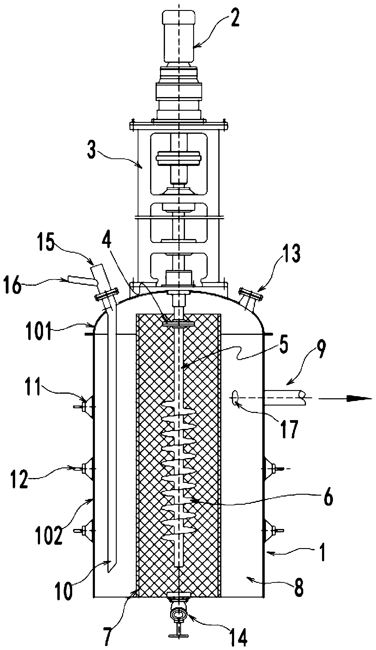
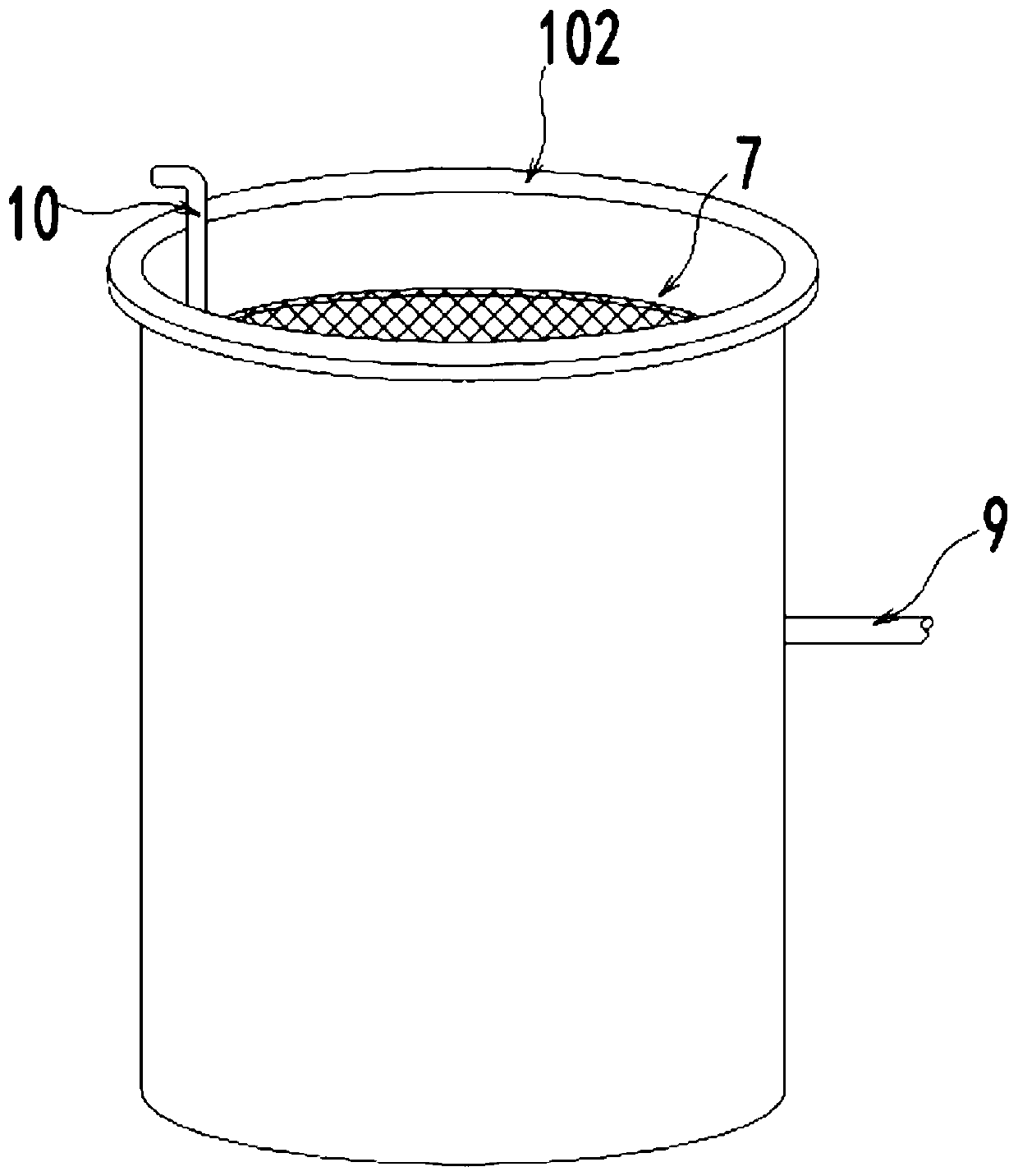
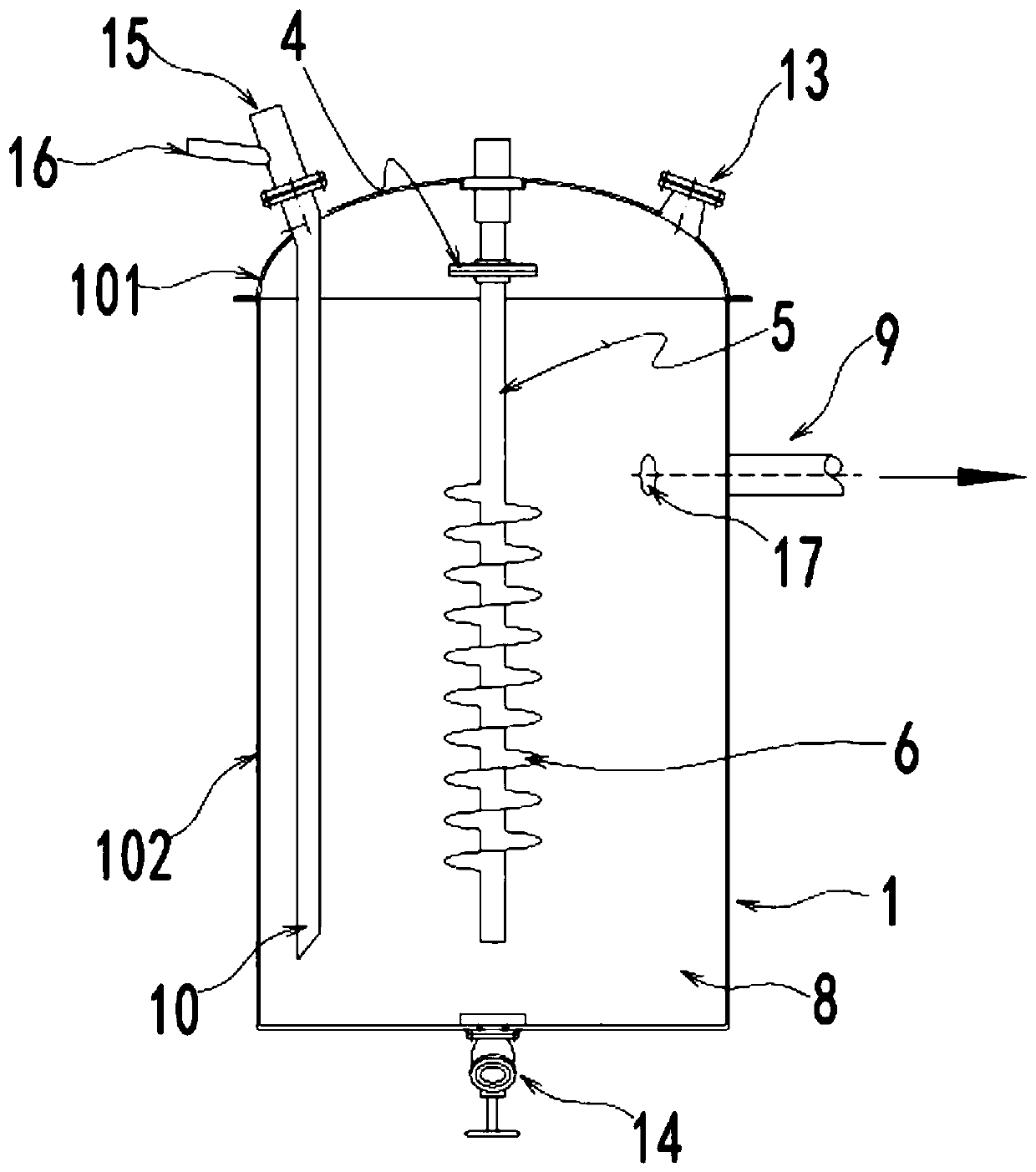
[0022] see Figure 1~3 , in an embodiment of the present invention, a soil beating mechanism includes a beating barrel 1, a motor reducer 2, a beating blade 6, an isolating cylinder 7 and a drain pipe 9, and the beating barrel 1 is fixed with an isolating cylinder coaxial with it 7. The isolation cylinder 7 is equivalent to a layer of isolation net, which is used to prevent clods, stones, etc. from entering the interior of the isolation cylinder 7. The outer wall of the isolation cylinder 7 and the inner wall of the beating barrel 1 form a beating area 8 for storing the soil mixture. The motor reducer 2 is installed on the beating barrel 1 through the motor mounting bracket 3. The beating shaft 5 is arranged in the isolation cylinder 7. The beating shaft 5 is driven to rotate by the motor reducer 2. The end of the beating shaft 5 passes through the flange plate 4 and the bolts. It is connected with the output end of the motor reducer 2, and the beating blade 6 is fixed on the ...

Embodiment 2

[0028] In an embodiment of the present invention, a soil remediation system includes the soil beating mechanism as described in the above embodiment, which can efficiently beat the soil so that pollutants such as heavy metal ions in the soil can remain in the water, and then After the water is settled, flocculated and other operations, the efficient restoration of the soil can be realized.

[0029] It should be noted that in this technical solution, by making the mud form a vortex, the internal particles of the mud collide with the soil clods during the movement, which can further promote the dissolution of the soil clods. The shock wave can make pollutants such as heavy metal ions inside the soil enter the water, which is convenient for subsequent centralized treatment; in addition, the design of the isolation cylinder 7 can prevent hard substances such as stones in the water from entering the interior of the isolation cylinder 7, and will not cause the beating blades 6 damag...


PUM


Abstract

The invention discloses a soil beating mechanism and relates to the technical field of soil remediation. The soil beating mechanism comprises a beating barrel, a motor reducing gear, beating blades, an isolation barrel and a liquid drain pipe, wherein the isolation barrel coaxial with the beating barrel is fixed in the beating barrel, the outer wall of the isolation barrel and the inner wall of the beating barrel form a beating area for storing a soil mixed liquid, the motor reducing gear is mounted on the beating barrel through a motor mounting support, a beating shaft is arranged in the isolation barrel, the beating shaft is driven by the motor reducing gear to rotate, the beating blades are fixed on the beating shaft to drive the soil mixed liquid to form vortex, and a liquid inlet pipeand a soil sending port are arranged on the beating barrel. The soil beating mechanism has the benefits as follows: mud forms vortex, inner particles collide with soil blocks during movement of the mud, dissolution of the soil blocks can be better promoted, and meanwhile, in cooperation with ultrasonic waves and impact waves formed by continuous gathering and breaking of bubbles, pollutants suchas heavy metal ions in soil can enter water.

Description

technical field [0001] The invention relates to the technical field of soil restoration, in particular to a soil beating mechanism and a soil restoration system. Background technique [0002] Soil remediation is a technical measure to restore the normal function of polluted soil. In the soil remediation industry, there are more than one hundred existing soil remediation technologies, and there are more than ten commonly used technologies, which can be roughly divided into three methods: physical, chemical and biological. Since the 1980s, many countries in the world, especially developed countries, have formulated and carried out plans for the treatment and restoration of contaminated soil, thus forming a new soil restoration industry. [0003] Generally speaking, soil remediation uses physical, chemical and biological methods to transfer, absorb, degrade and transform pollutants in the soil to reduce its concentration to an acceptable level, or convert toxic and harmful pol...

Claims


Application Information

Patent Timeline
IPC IPC(8): B09C1/00B02C13/14B02C13/284B02C19/18
CPCB02C13/14B02C13/284B02C19/18B02C2013/145B09C1/00
Inventor 周慧
Owner 周慧
Features
  • Generate Ideas
  • Intellectual Property
  • Life Sciences
  • Materials
  • Tech Scout
  • Unparalleled Data Quality
  • Higher Quality Content
  • 60% Fewer Hallucinations
Learn More