
Current-carrying friction and wear testing machine for pantograph slide plate and its application method

A pantograph sliding plate and current-carrying friction technology, which is applied in the field of mechanical devices, can solve the problems of poor service environment of the pantograph and catenary system, and the experimental research cannot meet the requirements, etc., and achieves the effect of simple and easy structure, easy implementation and high reliability.

Active Publication Date: 2020-03-24
INST OF MECHANICS CHINESE ACAD OF SCI
View PDF8 Cites 1 Cited by
  • Summary
  • Abstract
  • Description
  • Claims
  • Application Information

AI Technical Summary

Problems solved by technology

With the increase of train speed, the service environment of the pantograph-catenary system is even harsher. The existing experimental research on skateboards cannot meet the needs. Research on the damage mechanism of the slide plate, so as to explore the method of reducing the wear of the skateboard

Method used


Image

  • Current-carrying friction and wear testing machine for pantograph slide plate and its application method
  • Current-carrying friction and wear testing machine for pantograph slide plate and its application method
  • Current-carrying friction and wear testing machine for pantograph slide plate and its application method

Examples


Embodiment Construction

[0043] For example, certain words are used in the description and claims to refer to specific components. Those skilled in the art should understand that hardware manufacturers may use different terms to refer to the same component. This specification and claims do not use differences in names as a way to distinguish components, but use differences in functions of components as a criterion. If the "include" mentioned in the entire specification and claims is an open term, it should be interpreted as "include but not limited to". "Approximately" means that within the acceptable error range, those skilled in the art can solve the technical problem within a certain error range, and basically achieve the technical effect. The subsequent description of the specification is a preferred embodiment for implementing the application, but the description is for the purpose of explaining the general principles of the application and is not intended to limit the scope of the application. ...


PUM


Abstract

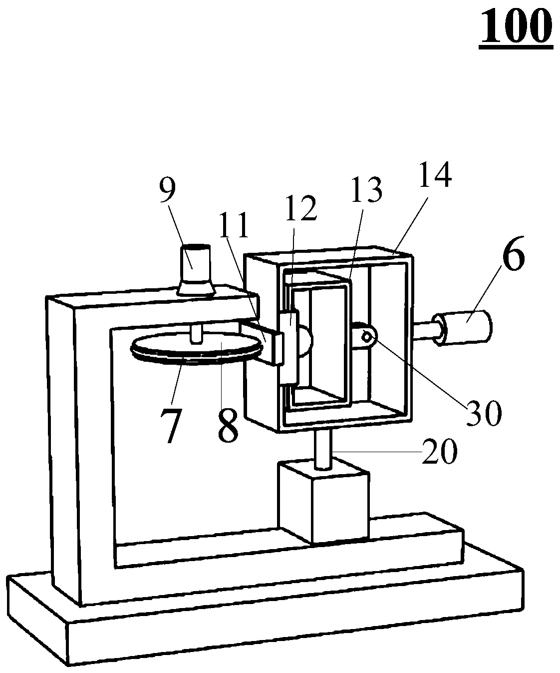
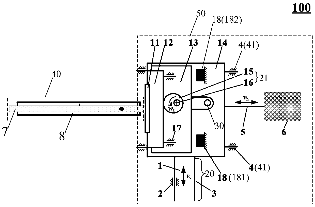
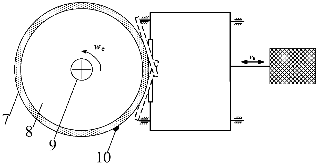
The invention discloses a current-carrying friction wear testing machine for a pantograph slide plate and a using method, and relates to the technical field of mechanical devices, wherein a contact line mounting structure comprises a rotating disc, a first driving motor, a contact line and a convex point; the contact line and the convex point rotate along with the rotating disc under the driving of the first driving motor; a pantograph slide plate mounting structure comprises a slide plate, a mounting frame, a swing frame, a main frame, a first movement control device, a swing control device,a second movement control device and a pressure control device; the mounting frame applies pressure to the sliding plate to change the contact pressure between the sliding plate and the contact line or the convex point; the slide plate swings under the driving of the swing control device, horizontally moves relative to the r rotating disc under the driving of the first movement control device, andvertically moves relative to the rotating disc under the driving of the second movement control device. Therefore, a service environment close to a bow net system is created, and a sliding plate damage mechanism under the coupling action of mechanical impact and thermal shock can be simulated.

Description

Technical field [0001] This application relates to the technical field of mechanical devices, in particular to a current-carrying friction and wear tester for pantograph sliding plates and a method of use. Background technique [0002] The pantograph slide plate and the contact wire form a pair of special friction pairs coupled mechanically and electrically. When the train is running at high speed, the friction pair with high current will generate obvious heat, especially when the pantograph is separated from the arc discharge, the great heat energy is released, instantaneous and concentrated, causing serious damage to the contact parts of the friction pair, worsening the working condition of the friction pair surface, and the quality of current receiving Deterioration affects the traction power supply performance of the train, and may cause major accidents in severe cases. [0003] At present, the localization rate of pantograph in my country's rail transit industry is relatively...

Claims


Application Information

Patent Timeline
Patent Type & Authority Patents(China)
IPC IPC(8): G01N3/56G01N3/02
CPCG01N3/02G01N3/56G01N2203/0005G01N2203/0246G01N2203/0682
Inventor 纪占玲郭迪龙李新宁杨国伟宋鑫郭易姚永芳刘雯
Owner INST OF MECHANICS CHINESE ACAD OF SCI
Learn More