Real-time positioning method and device based on machine vision

A real-time positioning, machine vision system technology, applied in the direction of instruments, computer parts, character and pattern recognition, etc., to achieve the effect of fast matching, improved stability and processing speed, and stable feature recognition

Active Publication Date: 2019-08-30
仇永生
View PDF3 Cites 1 Cited by
  • Summary
  • Abstract
  • Description
  • Claims
  • Application Information

AI Technical Summary

Problems solved by technology

The inertial measurement unit (IMU) can measure the angular velocity and acceleration through the built-in gyroscope and accelerometer, and then estimate the attitude of the camera, but there is a cumulative error in the estimated attitude

Method used


Image

  • Real-time positioning method and device based on machine vision
  • Real-time positioning method and device based on machine vision
  • Real-time positioning method and device based on machine vision

Examples


Embodiment Construction

[0030] The technical contents of the present invention will be further described below in conjunction with the examples; the following examples are illustrative, not restrictive, and the protection scope of the present invention cannot be limited with the following examples.

[0031] 1. Overall system plan

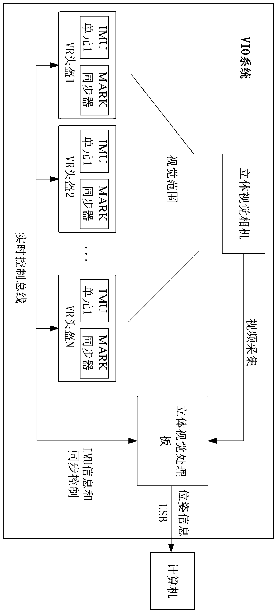
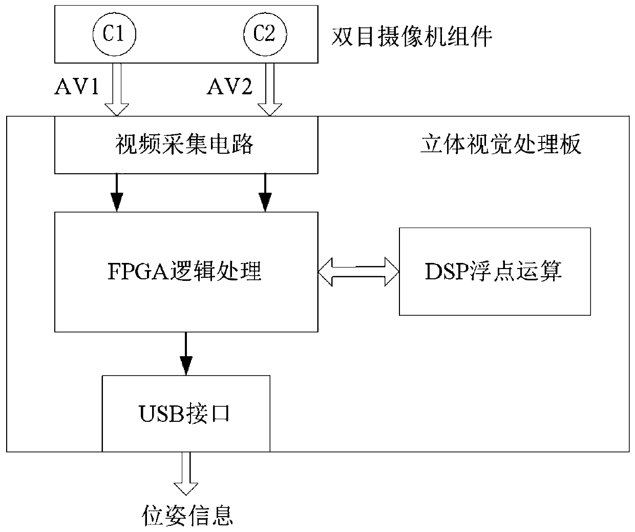
[0032] Such as figure 1 As shown, the system consists of a stereo vision camera, a VR helmet unit, a stereo vision processing board and a computer. The VR helmet unit includes an IMU module and a MARK synchronizer. A computer includes a processor and memory. Preferably, the stereo vision camera is a binocular camera assembly.

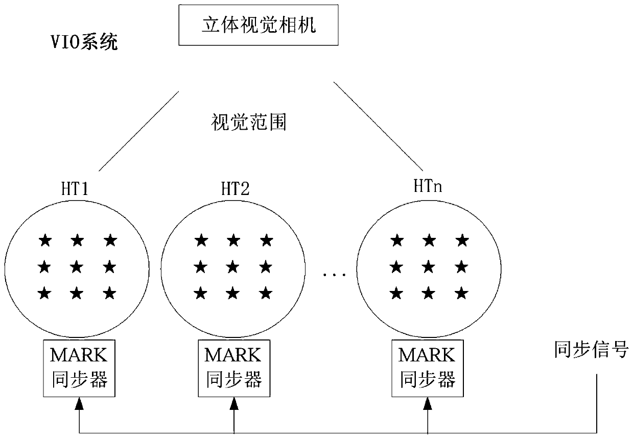
[0033] Set N VR helmets within the visual range of the stereo vision camera, where N is a natural number. The data collected by the IMU module and MARK synchronizer on each VR helmet unit are sent to the stereo vision processing board through the real-time control bus of the system. The stereo vision processing board acquires video acquisition ...


PUM


Abstract

The invention discloses a real-time positioning method and device based on machine vision. The device comprises a stereoscopic vision camera, a VR helmet unit, a stereoscopic vision processing board and a computer. The MARK point and the design of MARK synchronous control are added on the basis of a visual inertial odometry (VIO), so that the real-time response and the reliability of the system are improved.

Description

technical field [0001] The invention belongs to the field of machine vision, and in particular relates to a real-time positioning method and device based on machine vision. Background technique [0002] Machine vision aims to use computers to recognize and understand what is in images / videos. Positioning and posture determination technology is a technology that digitizes the position and posture of actions through physical means such as inertia and optics, and belongs to a branch of machine vision. The current mainstream motion capture technology includes optical motion capture technology and inertial motion capture technology. International mainstream optical motion capture technology research mainly includes British Oxford Metrics Limited, American MotionAnalysis and American Natural Point, which have developed Vicon system, Raptor system and OptiTrack system respectively. The tracking frequency of these systems is greater than 60Hz, and the tracking accuracy is low down...

Claims


Application Information

Patent Timeline
IPC IPC(8): G06T5/00G06T7/33G06T7/73G06T19/00G06K9/62
CPCG06T19/006G06T7/75G06T7/33G06T2207/20032G06V10/757G06T5/70
Inventor 仇永生吴加佳王勇梁志伟
Owner 仇永生
Why Eureka
Try Eureka