User-level comprehensive energy system optimization scheduling method based on multiple time scales

A comprehensive energy system and multi-time scale technology, applied in the direction of system integration technology, information technology support system, resources, etc., can solve problems such as unconsidered, low work efficiency, large error, etc., and achieve the effect of reducing operating costs

Pending Publication Date: 2019-09-03
SOUTHEAST UNIV
View PDF1 Cites 15 Cited by
  • Summary
  • Abstract
  • Description
  • Claims
  • Application Information

AI Technical Summary

Problems solved by technology

However, further attention needs to be paid to the fact that the response characteristics of electricity, heat, and gas multi-energy are different on the time scale, so it is often not considered or cannot be integrated and To overcome the difference in the time scale of the corre

Method used


Image

  • User-level comprehensive energy system optimization scheduling method based on multiple time scales
  • User-level comprehensive energy system optimization scheduling method based on multiple time scales
  • User-level comprehensive energy system optimization scheduling method based on multiple time scales

Examples


Embodiment 1

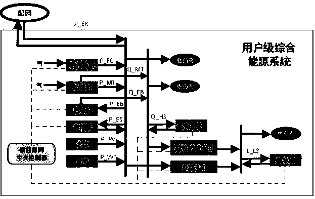
[0063] This embodiment is applied in an integrated energy system, and the structure of the integrated energy system is as follows figure 1 shown.

[0064] A user-level comprehensive energy system optimization scheduling method based on multiple time scales, comprising the following steps:

[0065] Step S1, obtain the basic operating parameters of the integrated energy system. The basic parameters in this embodiment include renewable energy sources such as photovoltaics and wind power, as well as the intraday forecast output of cooling, heating and electric loads, micro-combustion engines, electric boilers, fuel cells, absorption The capacity and climbing constraints of type refrigerators, electric refrigerators, batteries, heat storage tanks, cold storage tanks and other equipment, the interactive power constraints of the upper power grid connection line, and the purchase and sale price of power grid.

[0066] Step S2, establishing an optimal scheduling model for the day-ahea...

Embodiment 2

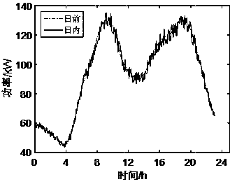
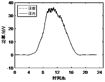
[0148] The user-level comprehensive energy system structure diagram of this embodiment is shown in Figure 1. The equipment components in the system include: photovoltaic, wind power, fuel cell, micro-gas turbine, electric boiler, absorption refrigerator, electric refrigerator, electric energy storage, thermal Energy storage, ice storage tanks, etc., and perform power interaction with the upper-level distribution network. The basic data of photovoltaic, wind power and load include the forecast data of the day and the rolling correction data of the day as shown in Figure 2. Figure 2a It is the day-ahead data and intra-day data of electric load, Figure 2b is the day-ahead data and intra-day data of PV, Figure 2c is the day-ahead data and intra-day data of wind power, Figure 2d is the day-ahead data and intra-day data of heat load, Figure 2e is the day-ahead data and intra-day data of the cooling load; image 3 shown in Table 1;

[0149] Table 1 Relevant operating parame...


PUM


Abstract

The invention discloses a user-level comprehensive energy system optimization scheduling method based on multiple time scales, and the method comprises the steps: building an objective function and aconstraint condition of the day-ahead and day-inside two-stage optimization scheduling of a comprehensive energy system, and providing a controllable unit start-stop plan and output for ensuring the economic and environment-friendly operation of the system in the day-ahead stage; in intra-day stage, achieving hierarchical control according to dynamic characteristics and time constant differences of cold and hot energy and electric energy, wherein the upper layer stabilizes the cold and hot energy power fluctuation with long scheduling duration, and the lower layer stabilizes electric energy power fluctuation with short scheduling time; and correcting the unit output through unit regulation and control penalty cost guidance and adjustment range constraint rolling. Economic and environment-friendly operation of the system can be achieved, prediction deviation of cold and hot energy loads, electric energy loads and renewable energy sources can be compensated in a layering mode along withreduction of the time scale, and safe, stable, efficient and economical operation of the comprehensive energy system is guaranteed.

Description

[0001] Field [0002] The invention belongs to the field of comprehensive energy systems, and in particular relates to a user-level comprehensive energy system optimization scheduling method based on multiple time scales. Background technique [0003] Energy is the foundation of human survival and development. The traditional energy system construction tends to plan, design and operate independently for each subsystem. There are differences and barriers in the development of different energy supply systems, and the coupling degree of multi-energy systems such as electricity, heat and gas is different. High, the lack of multi-energy complementarity and coordinated control mechanisms among them may lead to problems such as low energy utilization efficiency, insufficient system operation safety, and lack of system self-healing ability under failure conditions. [0004] In recent years, energy technologies such as distributed power generation, renewable energy, cogeneration, micro...

Claims


Application Information

Patent Timeline
IPC IPC(8): G06Q10/04G06Q10/06G06Q50/06H02J3/24H02J3/38H02J3/46
CPCH02J3/382G06Q10/04G06Q10/06312G06Q50/06H02J3/46H02J3/24H02J2203/20Y04S10/50Y02E40/70
Inventor 王琦陶苏朦汤奕
Owner SOUTHEAST UNIV
Why Eureka
Try Eureka