Solid waste pyrolysis and oil gas catalytic reforming system

A catalytic reforming and solid waste technology, applied in incinerators, hydrocarbon oil treatment, petroleum industry, etc., can solve the problems of easy condensation of pyrolysis oil, blockage of pipelines, unstable operation of pyrolysis system, etc.

Active Publication Date: 2021-05-04
CHINESE RES ACAD OF ENVIRONMENTAL SCI
View PDF3 Cites 2 Cited by
  • Summary
  • Abstract
  • Description
  • Claims
  • Application Information

AI Technical Summary

Problems solved by technology

However, pyrolysis oil is easy to condense and coke to block pipelines and equipment, making the operation of the

Method used


Image

  • Solid waste pyrolysis and oil gas catalytic reforming system

Examples


Embodiment 1

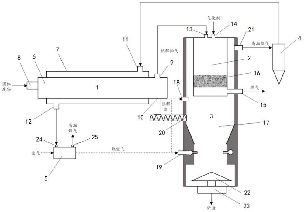
[0066] use figure 1 The shown solid waste pyrolysis and oil-gas catalytic reforming system processes agricultural straw as follows:

[0067] Agricultural straw enters the pyrolysis chamber 6 from the feed port 8, and undergoes a pyrolysis reaction at 550°C to obtain pyrolysis oil gas and pyrolysis charcoal. The components of the pyrolysis oil are high-temperature pyrolysis oil, CH 4 、H 2 , CO, CO 2 and small amounts of hydrocarbon gases;

[0068] The pyrolysis oil gas enters the catalytic reforming reactor 2 from the oil gas inlet 13, and H is added from the gasification agent inlet 14 2 O and O 2 Gasification agent, H 2 O and O 2 The amount of gasification agent introduced is 25% and 30% of the mass of oil and gas respectively, and the catalytic reforming reaction is carried out at 800°C to obtain the composition of CH 4 、H 2 , CO, CO 2 The mixed gas, the resulting gas is discharged from the gas outlet 15; wherein the catalyst in the catalytic reforming reactor 2 is ...

Embodiment 2

[0074] use figure 1 The shown solid waste pyrolysis and oil-gas catalytic reforming system processes plastic waste in the following ways:

[0075] Plastic waste enters the pyrolysis chamber 6 from the feed port 8, and undergoes a pyrolysis reaction at 500°C to obtain pyrolysis oil gas and pyrolysis charcoal, wherein the components of the pyrolysis oil are high-temperature pyrolysis oil, CH 4 、H 2 , CO, CO 2 and small amounts of hydrocarbon gases;

[0076] The pyrolysis oil gas enters the catalytic reforming reactor 2 from the oil gas inlet 13, and H is added from the gasification agent inlet 14 2 O and O 2 Gasification agent, H 2 O and O 2 The amount of gasification agent introduced is 35% and 35% of the mass of oil and gas respectively, and the catalytic reforming reaction is carried out at 850°C, and the composition is CH 4 、H 2 , CO, CO 2 The gas, the gas obtained is discharged from the gas outlet 15; wherein the catalyst in the catalytic reforming reactor 2 is an ...


PUM


Abstract

The invention provides a solid waste pyrolysis and oil gas catalytic reforming system, and belongs to the technical field of solid waste treatment. Pyrolysis reaction is carried out in a pyrolysis cavity 6 of an external heating type pyrolysis furnace 1, obtained pyrolysis oil gas enters a catalytic reforming reactor 2 to be subjected to catalytic reforming reaction, and obtained fuel gas can be subjected to resource utilization such as internal combustion power generation, boiler power generation and production of high-added-value products; pyrolytic carbon generated by pyrolysis enters a combustion area 17 for combustion, and the generated heat can be used for supporting a catalytic reforming reaction; the flue gas generated by combustion is high-temperature flue gas, and after being subjected to dust removal treatment, the flue gas enters a heat exchange cavity 7 of the external heating type pyrolysis furnace 1 to provide heat for pyrolytic reaction; and the flue gas subjected to heat exchange enters a heat exchanger 4 to perform second heat exchange with air, and the obtained hot air enters a combustion furnace 3 to provide hot air for combustion of pyrolytic carbon.

Description

technical field [0001] The invention relates to the technical field of solid waste treatment, in particular to a solid waste pyrolysis and oil gas catalytic reforming system. Background technique [0002] Solid waste is widely produced in human life and production activities. With the development of economy and the improvement of life, the output of solid waste is increasing day by day. If it is not handled properly, it will pollute the atmosphere, soil and water. Combustible solid waste accounts for a relatively high proportion of solid waste, including domestic garbage, combustible sludge, waste plastics, packaging waste, industrial leather fertilizers, and wood processing waste, etc., which have extremely high potential for resource utilization. Pyrolysis technology is an emerging heat treatment technology, which uses the instability of organic components in solid waste to convert solid waste into three types of gas, liquid and solid with more stable components under anae...

Claims


Application Information

Patent Timeline
IPC IPC(8): C10G1/00C10B53/00C10B57/00F23G5/027
CPCC10G1/00C10G1/002F23G5/027C10B57/00C10B57/005C10B53/00C10G2300/1003Y02E20/12
Inventor 叶美瀛李鸣晓陈王觅孟繁华侯佳奇张军平郝艳
Owner CHINESE RES ACAD OF ENVIRONMENTAL SCI
Why Eureka
Try Eureka