Medical system control method, device and equipment and medium

A medical system and control method technology, applied in radiotherapy, health care informatics, radiological diagnostic equipment control, etc.

Inactive Publication Date: 2019-09-03
SHANGHAI UNITED IMAGING HEALTHCARE
View PDF5 Cites 5 Cited by
  • Summary
  • Abstract
  • Description
  • Claims
  • Application Information

AI Technical Summary

Problems solved by technology

[0004] Computed X-ray tomography relies heavily on a stationary subject. The reason is that, in order to minimize the damage caused by X-rays, only the part to be scanned is radiated. Therefore, once the part to be scanned is aligned with the ray emitting device , the subject is required to remain still until the end of the scan, otherwise the imaging quality of the scanned image will be affected, or if the subject’s movement range is too large, the image of the target scanning part will not be obtained, but the image of the non-target part A scan was performed, causing the current scan to fail
But in fact, the subject will move voluntarily or involuntarily during the scanning process, which will destroy the consistency and integrity of the projection data, and even cause artifacts in the final CT image, resulting in the failure of the current scan. Re-scanning is required, which undoubtedly increases the X-ray radiation dose received by the subject
Similarly, in the field of radiotherapy, in order to minimize the damage caused by X-rays to non-radiated parts, only the radiotherapy parts (such as lesions) are radiated. Therefore, once the radiotherapy part is aligned with the radiation emitting device, it is required If the subject keeps still, if the subject moves, the radiation cannot irradiate the radiotherapy part as it should, but irradiates the non-radiation treatment part, causing additional damage to the subject

Method used


Image

  • Medical system control method, device and equipment and medium
  • Medical system control method, device and equipment and medium
  • Medical system control method, device and equipment and medium

Examples


Embodiment 1

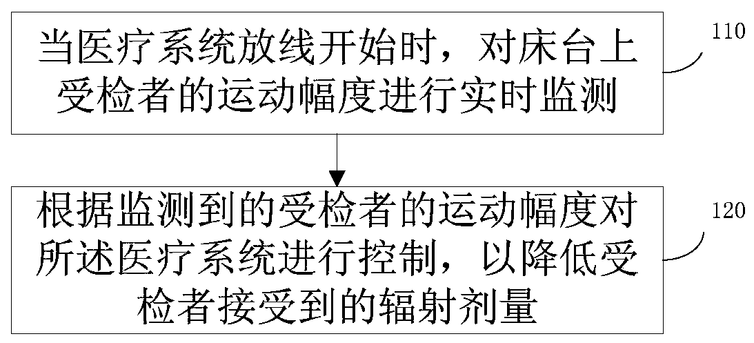
[0040] figure 1 It is a schematic flowchart of a medical system control method provided by Embodiment 1 of the present invention. The method is applicable to the situation that the medical system is automatically controlled according to the real-time motion of the examinee in the process of setting out the medical system, so as to reduce the radiation dose received by the examinee. The method can be executed by a medical system control device, which can be composed of software and / or hardware, and is generally integrated into a medical system, such as medical imaging equipment, radiotherapy equipment, and the like. see figure 1 As shown, the method specifically includes the following steps:

[0041] Step 110 , when the medical system starts to wire, monitor the range of motion of the subject on the bed in real time.

[0042] Wherein, the medical system may specifically be CT (Computed Tomography, computer tomography), MRI (Magnetic Resonance Imaging, magnetic resonance imag...

Embodiment 2

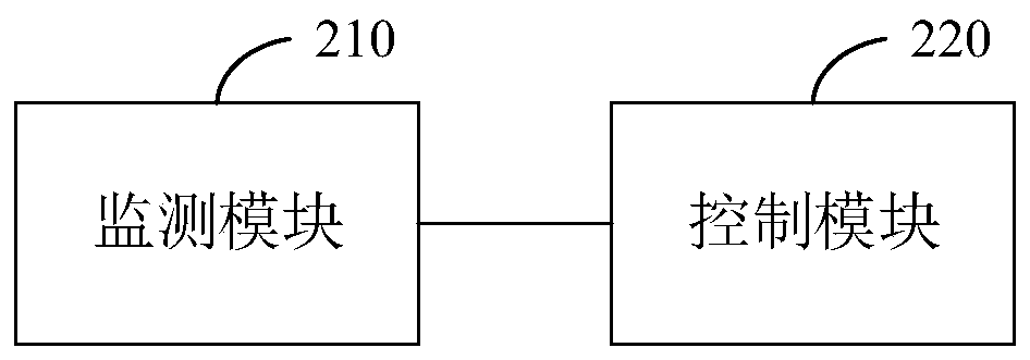
[0062] figure 2 It is a schematic structural diagram of a medical system control device provided by Embodiment 2 of the present invention. refer to figure 2 As shown, the medical system control device includes: a monitoring module 210 and a control module 220;

[0063] Among them, the monitoring module 210 is used to monitor the range of motion of the subject on the bed in real time when the medical system starts to discharge the wire; the control module 220 is used to monitor the range of motion of the subject according to the monitoring The system controls to reduce the radiation dose received by the subject.

[0064] Further, the control module 220 includes:

[0065] The first control unit is configured to control the movement of the bed according to the monitored subject's movement amplitude when the monitored subject's movement amplitude does not reach the limit threshold, so as to compensate the subject's movement, so that the subject The target part of the examine...

Embodiment 3

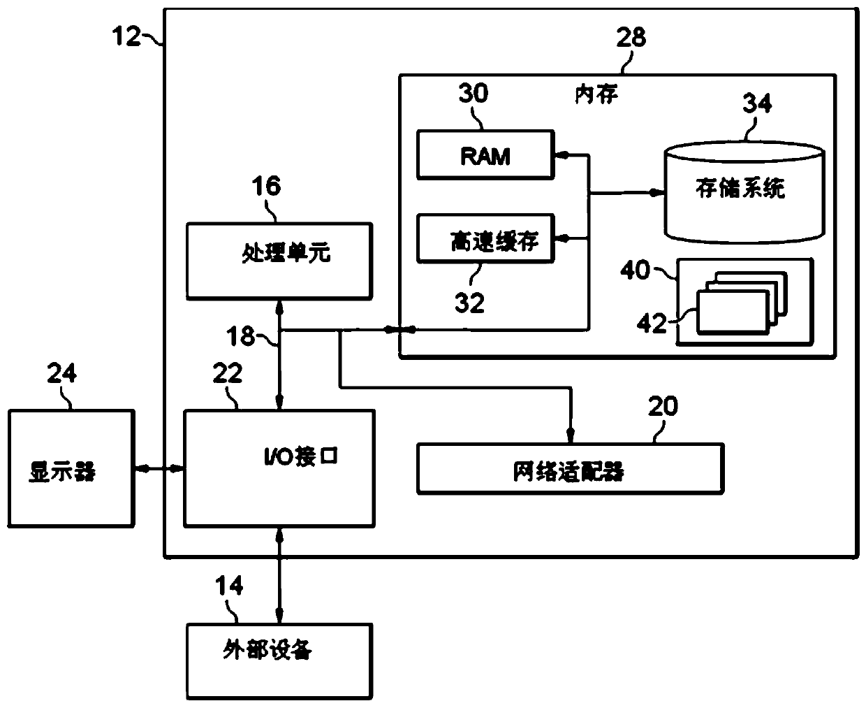
[0080] image 3 It is a schematic structural diagram of an electronic device provided in Embodiment 4 of the present invention. image 3 A block diagram of an exemplary device 12 suitable for use in implementing embodiments of the invention is shown. image 3 The shown device 12 is only an example and should not impose any limitation on the functions and scope of use of the embodiments of the present invention.

[0081] Such as image 3 As shown, device 12 takes the form of a general purpose computing device. Components of device 12 may include, but are not limited to: one or more processors or processing units 16, system memory 28, bus 18 connecting various system components including system memory 28 and processing unit 16.

[0082] Bus 18 represents one or more of several types of bus structures, including a memory bus or memory controller, a peripheral bus, an accelerated graphics port, a processor, or a local bus using any of a variety of bus structures. These archite...


PUM


Abstract

The embodiment of the invention discloses a medical system control method and device, equipment and a medium, and the method comprises the steps: carrying out the real-time monitoring of the movementamplitude of a subject on a bed when the medical system starts to pay off; and controlling the medical system according to the monitored movement amplitude of the subject so as to reduce the radiationdosage received by the subject. Through the technical scheme of the embodiment of the invention, the purpose of reducing the X-ray radiation dose received by the subject is achieved.

Description

technical field [0001] Embodiments of the present invention relate to intelligent medical imaging technology, and in particular to a medical system control method, device, equipment and medium. Background technique [0002] With the continuous development of medical technology, more and more medical imaging equipment (such as CT (Computed Tomography, computerized tomography)) are used in clinical In diagnosis and treatment. [0003] Taking a CT machine as an example, a CT machine generally has a frame and a bed. The gantry includes devices capable of emitting and receiving radiation, which emit radiation and convert received radiation signals into electrical signals for use in generating scan images. The bed platform is used to carry the subject (that is, the target to be scanned). Usually, after the subject is in position on the bed platform in a posture such as lying down or lying down, the bed platform moves the part to be scanned of the subject through its own movement...

Claims


Application Information

Patent Timeline
Patent Type & Authority Applications(China)
IPC IPC(8): G06T7/20G06T7/70G06T11/00G16H30/20A61N5/10A61B6/03A61B6/00
CPCA61B6/03A61B6/54A61B6/542A61N5/1064G06T7/20G06T11/008G06T7/70G16H30/20
Inventor 李兵
Owner SHANGHAI UNITED IMAGING HEALTHCARE
Why Eureka
Try Eureka