Detection method for preventing printing mixing during SE battery production process

A technology of production process and detection method, applied in circuits, electrical components, semiconductor/solid-state device testing/measurement, etc., can solve problems such as mixing, loss, and difficulty in observation, so as to achieve zero mixing in production lines and avoid losses. , to avoid the effect of a large number of mixed films

Active Publication Date: 2019-09-06
TONGWEI SOLAR (ANHUI) CO LTD
View PDF4 Cites 3 Cited by
  • Summary
  • Abstract
  • Description
  • Claims
  • Application Information

AI Technical Summary

Problems solved by technology

And because the laser doping step is relatively advanced in the production process after diffusion, the clarity after coating is not easy to observe. Therefore, for laser doped areas with different patterns, if employees do not carefully observe the product, it is easy to cause large production lines. Batch mixing, resulting in large losses
[0004] For existing SE+PERC products, when there are more than one type of cell products in the production process, because different types of cell products will have different laser patterns, resulting in different laser doping areas, and the laser doping area itself The recognizability is poor, and it is difficult to observe with the naked eye. As a result, before the subsequent laser grooving on the back, it is impossible to identify whether the cell model after SE laser doping is the same as the cell model applicable to the back laser grooving, for example: SE The cell after laser doping is a 4BB cell, and the cell is doped with three anti-break grid lines. At this time, the subsequent back laser slotting machine must be equipped with four laser slotting lines when laser slotting, so that Only then can a good laser slotting process be carried out correspondingly; and if there are three anti-break grid lines doped on the battery sheet, and the subsequent back laser slotting machine correspondingly has five or more laser slotting lines during laser slotting , so that the anti-break grid line and the laser slotting line cannot perform the corresponding slotting process, which will cause a large amount of mixed chips in subsequent production and cause losses. Therefore, it is necessary to identify the type of the SE laser-doped cell sheet, and Laser slotting for matching, and in actual production, if laser doping is not performed at the position of the anti-break grid line, it will cause poor EL of the product

Method used


Image

  • Detection method for preventing printing mixing during SE battery production process
  • Detection method for preventing printing mixing during SE battery production process
  • Detection method for preventing printing mixing during SE battery production process

Examples


Embodiment 1

[0032] The production process steps of SE battery with model 4BB are as follows:

[0033] 1. Pre-cleaning and suede preparation of P-type silicon wafers;

[0034] 2. Preparation of P-N junction: use thermal diffusion to prepare phosphorus diffusion layer, adjust N 2 amount, oxygen flow rate, amount of phosphorus source, and diffusion temperature, to prepare the required high-resistance diffusion layer of 100-180Ω;

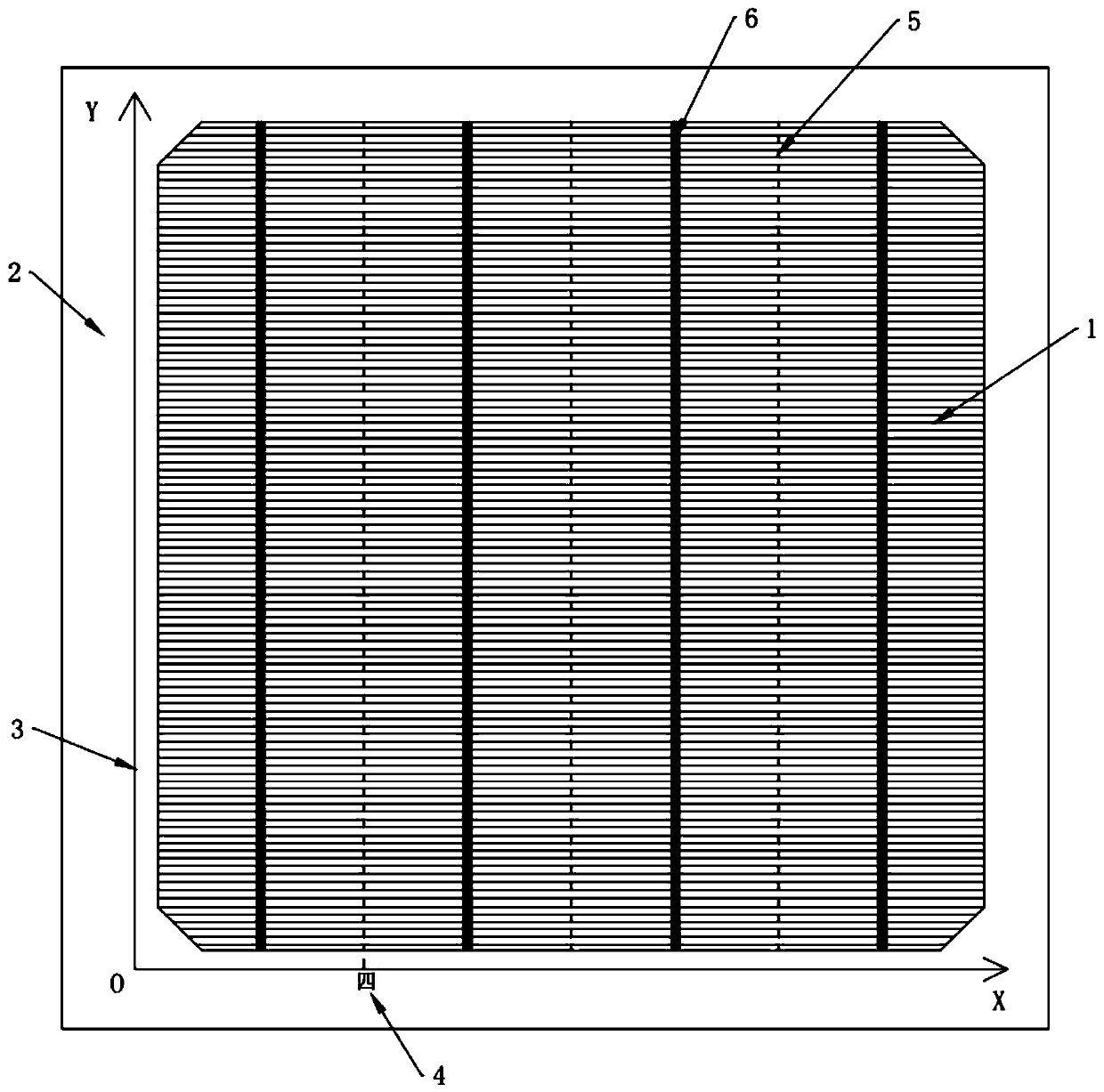
[0035] 3. SE laser doping: doping three anti-break grid lines 5 on the surface of the cell 1;

[0036] 4. Prepared by back etching to remove PSG, annealing, aluminum oxide passivation film and front and back SiNx layers;

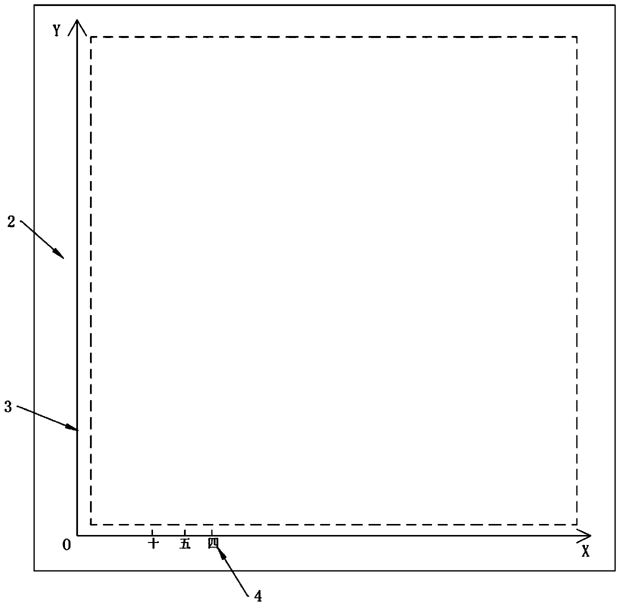
[0037] 5. Photo inspection steps: S1. Add a photo booth 2 before the laser slotting and loading area on the back, as attached to the manual figure 1 As shown, a dotted frame area with the same size as the cell 1 is set in advance on the photo stage 2 to place the cell 1, and a one-time coordinate system 3 is established on the surface of the p...

Embodiment 2

[0045] The production process steps of SE battery model 5BB are as follows:

[0046] 1. Pre-cleaning and suede preparation of P-type silicon wafers;

[0047] 2. Preparation of P-N junction: use thermal diffusion to prepare phosphorus diffusion layer, adjust N 2 amount, oxygen flow rate, amount of phosphorus source, and diffusion temperature, to prepare the required high-resistance diffusion layer of 100-180Ω;

[0048] 3. SE laser doping: doping four anti-break grid lines 5 on the surface of the cell 1;

[0049] 4. Prepared by back etching to remove PSG, annealing, aluminum oxide passivation film and front and back SiNx layers;

[0050] 5. Photo inspection steps: S1. Add a photo booth 2 before the laser slotting and loading area on the back, as attached to the manual figure 1 As shown, a dotted frame area with the same size as the cell 1 is set in advance on the photo stage 2 to place the cell 1, and a one-time coordinate system 3 is established on the surface of the photo s...

Embodiment 3

[0058] The steps of the production process of the SE battery whose model is a shingled module are as follows:

[0059] 1. Pre-cleaning and suede preparation of P-type silicon wafers;

[0060] 2. Preparation of P-N junction: use thermal diffusion to prepare phosphorus diffusion layer, adjust N 2 amount, oxygen flow rate, amount of phosphorus source, and diffusion temperature, to prepare the required high-resistance diffusion layer of 100-180Ω;

[0061] 3. SE laser doping: Doping ten anti-break grid lines 5 on the surface of the cell 1;

[0062] 4. Prepared by back etching to remove PSG, annealing, aluminum oxide passivation film and front and back SiNx layers;

[0063] 5. Photo inspection steps: S1. Add a photo booth 2 before the laser slotting and loading area on the back, as attached to the manual figure 1 As shown, a dotted frame area with the same size as the cell 1 is set in advance on the photo stage 2 to place the cell 1, and a one-time coordinate system 3 is establis...


PUM


Abstract

The invention discloses a detection method for preventing printing mixing during the SE battery production process. The step of shooting detection is added between SE laser doping and back-surface laser groove formation and is used for whether a batter piece after SE laser doping is consistent with the specification of a battery piece before the back-surface laser groove formation. A shooting table is additionally arranged between SE laser doping and back-surface laser groove formation, placement and detection of different types of battery pieces are handled by a coordinate system which is built in advance, contrast by camera shooting and a coordinate system is more convenient to identify compared with naked-eye observation, so that whether the type of the battery piece right subjected toSE laser doping is consistent with the type of the battery piece before back-surface laser groove formation is or not is determined, the situation that a large amount of pieces are mixed during subsequent production is prevented, and loss is prevented.

Description

technical field [0001] The invention relates to the technical field of printing and slotting of SE batteries, in particular to a detection method for preventing printing mixed sheets in the production process of SE batteries. Background technique [0002] With the continuous development of crystalline silicon technology, the expansion of solar cell production scale and the continuous reduction of cell prices, reducing production costs and improving efficiency are the focus of cell technology development. For existing conventional PERC cells, the front side has a higher junction depth and phosphorus concentration, and the high recombination of the reflector will lead to lower open voltage and short-circuit current, and the selective emitter (SE) electrode is because it receives Low-concentration doping in the illuminated area and high doping under the metal grid line form a lateral high-low junction structure to increase the potential difference between the P-N junctions, red...

Claims


Application Information

Patent Timeline
Patent Type & Authority Applications(China)
IPC IPC(8): H01L21/66
CPCH01L22/12H01L22/26
Inventor 杨蕾余波王涛丁士引
Owner TONGWEI SOLAR (ANHUI) CO LTD
Why Eureka
Try Eureka