A Harmonic Suppression Transmitter

A harmonic suppression and transmitter technology, applied in the field of transmitters, can solve the problems of large circuit area, high power consumption, and high transmitter power consumption, and achieve the purpose of reducing off-chip components, circuit power consumption, and chip area. Effect

Active Publication Date: 2021-03-09
SOUTHEAST UNIV
View PDF6 Cites 0 Cited by
  • Summary
  • Abstract
  • Description
  • Claims
  • Application Information

AI Technical Summary

Problems solved by technology

However, the oscillator, phase shifter and power amplifier in the current harmonic suppression transmitter also work at high frequency, which makes the power consumption of the transmitter higher
[0007] Therefore, the wireless radio frequency transmitter in the prior art has the defects of large power consumption and large circuit area; while the existing harmonic suppression transmitter does not require an LC network to suppress harmonic components, but still has relatively large power consumption The problem

Method used


Image

  • A Harmonic Suppression Transmitter
  • A Harmonic Suppression Transmitter
  • A Harmonic Suppression Transmitter

Examples


Embodiment 1

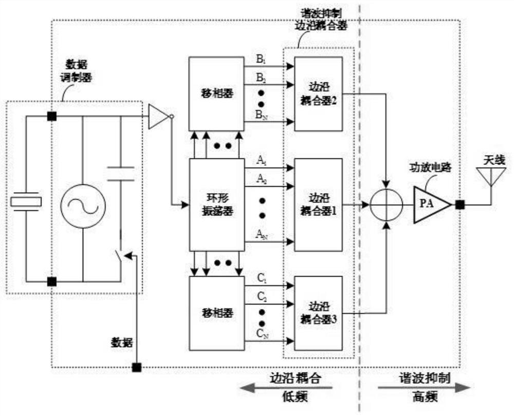
[0030] Embodiment 1: as figure 1 As shown, a harmonic suppression transmitter, the transmitter includes a data modulator, a ring oscillator, a phase shifter, a harmonic suppression edge coupler, a power amplifier circuit and an antenna;

[0031] The data modulator is used to receive a digital baseband signal to be transmitted, and modulate the signal to be transmitted to generate a low-frequency modulated signal;

[0032] The ring oscillator is used to generate a set of N channels of low-frequency signals with equal phase intervals according to the low-frequency modulated signal provided by the data modulator;

[0033] The phase shifter is used to perform phase-shift processing on the first group of low-frequency signals to generate the second group and the third group of N-channel low-frequency signals respectively; the harmonic suppression edge coupler is used for edge coupling of the low-frequency signals respectively , output N-fold frequency ladder wave;

[0034] The po...


PUM


Abstract

The invention discloses a harmonic suppression transmitter, comprising: a data modulator, a ring oscillator, a phase shifter, a harmonic suppression edge coupler, a power amplifier circuit and an antenna; wherein the data modulator is used to receive the digital baseband to be transmitted signal, and modulate the signal to be transmitted to generate a low-frequency modulated signal; a ring oscillator is used to output a set of low-frequency signals with equal phase intervals according to the low-frequency modulated signal provided by the data modulator; a phase shifter , used for phase-shifting the low-frequency signals to generate the second and third groups of low-frequency signals respectively; the harmonic suppression edge coupler is used for edge-coupling the three groups of low-frequency signals and outputting high-frequency steps Wave. In the harmonic suppression transmitter of this embodiment, the ring oscillator and the phase shifter all work at low frequencies, reducing circuit power consumption; they can output stepped waves that approximate sinusoidal signals, have harmonic suppression functions, and require no inductance-capacitor network, reducing circuit area.

Description

technical field [0001] The invention relates to a transmitter, in particular to a harmonic suppression transmitter, which belongs to the technical field of circuits and systems. Background technique [0002] Radio frequency transmitters are widely used in the communication field. The radio frequency transmitters in the prior art have a front-end circuit composed of a phase-locked loop, a mixer and a power amplifier. [0003] During the working process of the wireless radio frequency transmitter, the high-frequency signal and baseband signal generated by the phase-locked loop are modulated through the mixer, and the modulated radio frequency signal output by the mixer is transmitted through the power amplifier. [0004] The above-mentioned types of wireless radio frequency transmitters, phase-locked loops, mixers and power amplifiers all work at high frequencies, resulting in high system power consumption. In addition, the power supply of the relevant components of the baseb...

Claims


Application Information

Patent Timeline
Patent Type & Authority Patents(China)
IPC IPC(8): H04B1/04
CPCH04B1/04H04B1/0475H04B2001/0408
Inventor 王科平周于浩
Owner SOUTHEAST UNIV
Why Eureka
Try Eureka