Capillary communicating tube type differential pressure sensor and measuring method

A technology of differential pressure sensor and connecting pipe, applied in the direction of pressure difference measurement between multiple valves, measuring device, measuring fluid pressure, etc., can solve problems such as nonlinearity and large influence of temperature performance, achieve easy measurement and improve measurement The effect of sensitivity

Active Publication Date: 2019-09-10
CHINA JILIANG UNIV
View PDF12 Cites 4 Cited by
  • Summary
  • Abstract
  • Description
  • Claims
  • Application Information

AI Technical Summary

Problems solved by technology

The disadvantage is that there is a prominent contradiction between its sensitivity and frequency response, and the temperature has a greater impact on the performance of this sensor
Capacitive sensors have the advantages of simple structure, high sensitivity, good dynamic response characteristics, strong overload resistance, and strong adaptability to harsh conditions such as high temperature, radiation, and strong vibration. The disadvantages are nonlinear output characteristics, parasitic capacitance, and distributed capacitance. Influence on sensitivity and measurement accuracy, etc.

Method used


Image

  • Capillary communicating tube type differential pressure sensor and measuring method
  • Capillary communicating tube type differential pressure sensor and measuring method
  • Capillary communicating tube type differential pressure sensor and measuring method

Examples


Embodiment Construction

[0026] The present invention will be further described below in conjunction with the examples.

[0027] The following examples are used to illustrate the present invention, but cannot be used to limit the protection scope of the present invention. The conditions in the embodiment can be further adjusted according to the specific conditions, and the simple improvement of the method of the present invention under the premise of the concept of the present invention belongs to the protection scope of the present invention.

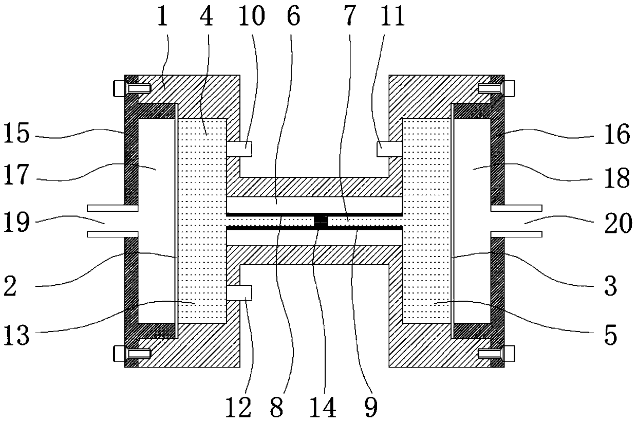
[0028] Such as figure 1 As shown, a capillary communicating tube type differential pressure sensor includes an "H" shaped casing 1, a first elastic diaphragm 2 and a second elastic diaphragm 3, and the casing 1 and the first elastic diaphragm 2 and the second elastic diaphragm 3 respectively form the first cavity 4 and the second cavity 5 which communicate with each other, an insulating capillary communication tube 6 is provided between the first cavity 4 and...


PUM


Abstract

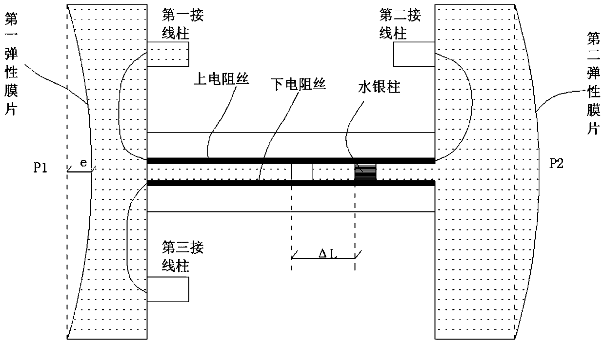
The invention discloses a capillary communicating tube typedifferential pressure sensor. A shell and a first elastic diaphragm and a second elastic diaphragm form a first cavity and a second cavity which are internally filled with insulating colloids, the first cavity and the second cavity communicate to each other, and a capillarycommunicating tubewith a slender capillary tube is disposed betweenthe first cavity and the second cavity. An upper resistance wireand a lower resistance wire of the same material and shape are embedded in the upper inner walland the lower inner wall of the capillary tube correspondingly, anda mercury column is arranged at the center point betweenthe upper resistance wireand the lower resistance wire in the longitudinal direction. The mercury column separates the insulating colloids on both sides, the upper resistance wire is externally connected with two binding posts correspondingly, and the lower resistance wire is externally connected with one binding post. When the ambient pressure difference ismeasured specifically and external connected pressure is applied on the first elastic diaphragm and the second elastic diaphragm, the mercury column is pushed to displace to deviate away from the center point of the resistance wires, the resistance valuebetween the binding posts of the upper resistance wire and the lower resistance wire and the resistanceof the whole resistance wires are measured at this time, the displacement of the mercury column deviating from the center point can be obtained, and then differential pressure on the two sides is derived.

Description

technical field [0001] The invention belongs to the technical field of differential pressure measurement, and in particular relates to a capillary communicating tube type differential pressure sensor. Background technique [0002] A differential pressure sensor is a sensor used to measure the difference between two pressures, usually used to measure the pressure difference between the front and back ends of a device or component. Differential pressure sensors are widely used in many high-precision measurement occasions such as micro-flow measurement, leak testing, clean room monitoring, environmental tightness testing, gas flow measurement, and liquid level measurement. [0003] At present, there are mainly two types of differential pressure sensors: piezoresistive and capacitive. The main pressure measuring part of the piezoresistive differential pressure sensor is a silicon piezoresistive sensor chip. The core part of the chip is a silicon diaphragm, on which four equal r...

Claims


Application Information

Patent Timeline
Patent Type & Authority Applications(China)
IPC IPC(8): G01L13/02
CPCG01L13/026
Inventor 张洪军
Owner CHINA JILIANG UNIV
Why Eureka
Try Eureka