Pitch angle imaging method based on vortex electromagnetic waves

A vortex electromagnetic wave and imaging method technology, applied in the reflection/re-radiation of radio waves, radio wave measurement systems, instruments, etc., can solve the problems of limited antenna frequency bandwidth, wide scanning range, unfavorable accurate imaging, etc. The effect of precision, wide imaging range, and low antenna bandwidth

Active Publication Date: 2019-09-10
UNIV OF ELECTRONIC SCI & TECH OF CHINA
View PDF7 Cites 10 Cited by
  • Summary
  • Abstract
  • Description
  • Claims
  • Application Information

AI Technical Summary

Problems solved by technology

The disadvantages of this method are: (1) figure 2 As shown, when the excitation signal frequency is higher than 2.4GHz or lower than 1GHz, the maximum gain angle θ max The change trend of the antenna has been very slow, and the actual antenna frequency bandwidth is limited, and it is impossible to achieve a large span of excitation frequency, so a wide scanning range

Method used


Image

  • Pitch angle imaging method based on vortex electromagnetic waves
  • Pitch angle imaging method based on vortex electromagnetic waves
  • Pitch angle imaging method based on vortex electromagnetic waves

Examples


Embodiment Construction

[0040] In order to make the objectives, technical solutions and advantages of the present invention clearer, the present invention will be further described in detail below in conjunction with the embodiments and the drawings.

[0041] The invention uses the simulation software FEKO, and establishes the vortex electromagnetic wave imaging model in the software. The antenna element in the present invention can be a horn antenna, a patch antenna, etc. In the simulation, an ideal dipole antenna is used as the antenna element, and it is assumed that the azimuth angle of the target is known.

[0042] A pitch angle imaging method based on vortex electromagnetic waves includes the following steps:

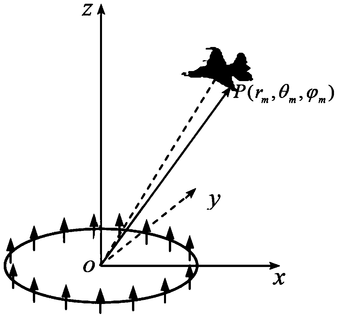
[0043] Step 1: Set up the radar antenna: The radar is composed of a uniform loop antenna array composed of N=30 antenna elements on a circle with a radius of a=50mm. The coordinate system is established with the center of the circle as the origin of the coordinates and the normal direction of th...


PUM


Abstract

The invention provides a pitch angle imaging method based on vortex electromagnetic waves, and belongs to the field of radar target imaging. The traditional method is based on electromagnetic wave amplitude scanning, the amplitude scanning range of the traditional method is limited by the working bandwidth of an antenna, and is different from the traditional pitch angle imaging based on vortex electromagnetic waves. The pitch angle imaging method based on vortex electromagnetic waves can work at a single frequency point based on the phase information of an echo signal, so that the pitch angleimaging range is wide, and the requirement on the bandwidth of the antenna is low. The accuracy of amplitude scanning of the traditional method depends on the width of an electromagnetic beam, and thenarrower the electromagnetic beam is, the higher the imaging accuracy is, but the narrower electromagnetic beam is difficult to realize. The imaging precision of the pitch angle imaging method basedon vortex electromagnetic waves depends on the grid thickness during discretization of the pitch angle, and the imaging precision can be effectively improved by adopting thinner grids. The pitch angleimaging method based on vortex electromagnetic waves can realize the measurement of the pitch angle of 5-85 degrees, has wide measurement range, and has the imaging error lower than 1.2 degrees in the range of the pitch angle of 5-85 degrees.

Description

Technical field [0001] The invention belongs to the field of radar target imaging, and in particular relates to a method for imaging a pitch angle based on vortex electromagnetic waves. Background technique [0002] At present, radar imaging is mainly based on the three characteristics of electromagnetic wave amplitude, frequency and phase for amplitude modulation, frequency modulation and phase modulation information modulation, which mainly uses far-field plane wave approximation. In 1992, the Dutch physicist L. Allen discovered that the Laguerre-Gaussian laser beam carries orbital angular momentum (OAM), that is, the wavefront of the Laguerre-Gaussian laser beam is no longer a plane, but rotates around the direction of propagation, forming Swirly. Therefore, the vortex electromagnetic wave is an electromagnetic wave carrying orbital angular momentum, and its phase wave front is spiral. Since vortex electromagnetic waves provide additional degrees of freedom for information m...

Claims


Application Information

Patent Timeline
IPC IPC(8): G01S13/89
CPCG01S13/89
Inventor 雷世文李睿明胡皓全林志鹏陈波唐璞田径包永芳何子远杨伟
Owner UNIV OF ELECTRONIC SCI & TECH OF CHINA
Why Eureka
Try Eureka