Design methods of synchronous motors

A design method and motor technology, applied in the control of generators, motor-generator control, electronic commutation motor control, etc., can solve the problems of slow convergence of two-dimensional electromagnetic field finite element analysis method, long calculation time, inability to meet rapid design and other problems

Active Publication Date: 2019-09-10
SHANGHAI MOTOR SYST ENERGY SAVING ENG TECH RES CENT +2
View PDF7 Cites 5 Cited by
  • Summary
  • Abstract
  • Description
  • Claims
  • Application Information

AI Technical Summary

Problems solved by technology

However, the more accurate three-dimensional electromagnetic field finite element analysis method takes a long time to calculate and cannot meet the needs of rapid design; the two-dimensional electromagnetic field finite element analysis method, although the calculation speed is faster, can only calculate the performance of the motor iron core more accurately. The influen

Method used


Image

  • Design methods of synchronous motors
  • Design methods of synchronous motors
  • Design methods of synchronous motors

Examples


Embodiment 1

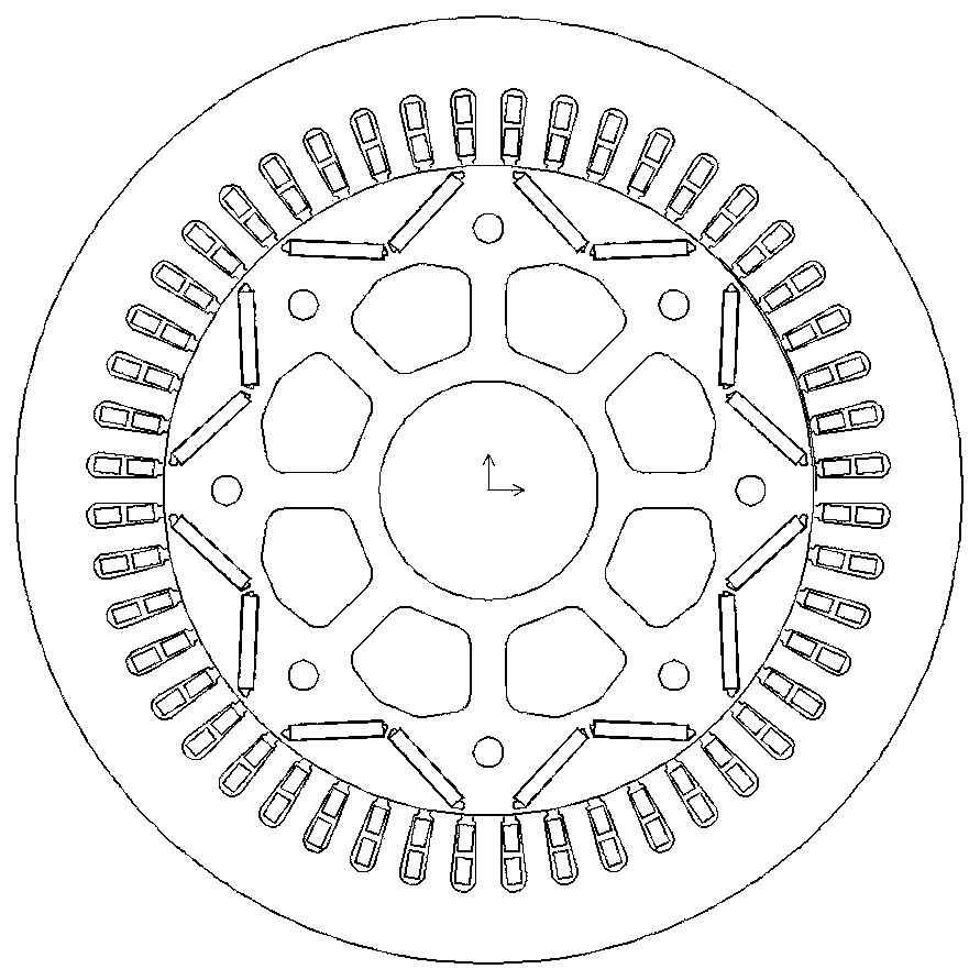
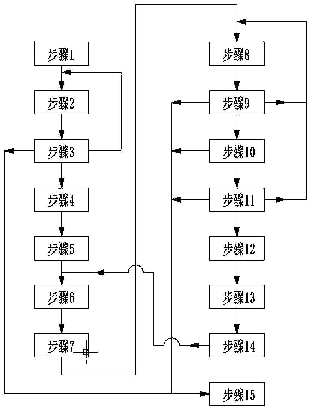
[0194]Design a 22kW, 1500r / min three-phase permanent magnet synchronous motor with a rated voltage of 380V, a frame size of 160, a stator outer diameter of 260mm, a stator inner diameter of 180mm, a stack length of 200mm, an air gap of 0.7mm, and a rotor inner diameter of 60mm. Built-in V-shaped structure, the magnetic steel adopts N38UH NdFeB permanent magnet material, the stator and rotor core material is 35WW300 silicon steel sheet, the stator winding star connection, double-layer stacked winding, the number of conductors per slot is 30, parallel branch 4, the wire is Three 0.8mm enamelled round copper wires are wound together. The section of the stator and rotor punching and winding of the three-phase permanent magnet synchronous motor is as follows: figure 1 As shown, the design process is as follows figure 2 shown.

[0195] step 1,

[0196] The 2D electromagnetic field transient motion model of the motor is established in Ansoft Maxwell 2D. The parameters of the main...

Embodiment 2

[0351] Embodiment 2 adopts the same electromagnetic parameters of the three-phase permanent magnet synchronous motor as the embodiment, and the output power and voltage are also the same. Design flow chart such as figure 2 shown.

[0352] step 1,

[0353] Establish the 2D electromagnetic field transient motion model of the motor to be designed in Ansoft Maxwell 2D. The parameters of the main materials and dimensions are the same as those based on the magnetic circuit analysis method. The current source is used for excitation and set to zero current, especially in the material setting Check the core material loss characteristic parameters and select the stator core part in the Excitations>Set Core Loss menu. Calculate a period (10ms) of the electromagnetic field that rotates at a certain speed, and the step size is 1 / 100 of the period, that is, 0.1ms. Obtain the excitation electromotive force curve on any phase coil of the period through the post-processing software, and pe...

Embodiment 3

[0511] Design a 7.5kW, 1500r / min three-phase synchronous reluctance motor, rated at 380V, using a frame size of 160, with a stator outer diameter of 260mm, a stator inner diameter of 180mm, a stack length of 200mm, an air gap of 0.7mm, and a rotor inner diameter of 60mm. Multi-layer magnetic barrier structure, stator and rotor core material is 35WW300 silicon steel sheet, stator winding star connection, double-layer stacked winding, 40 conductors per slot, 4 parallel branches, and two 0.85mm enamelled round copper wires are wound together. Stator and rotor punching and winding section of three-phase synchronous reluctance motor Figure 9 shown. Design flow chart such as Figure 11 shown.

[0512] step 1,

[0513] Set direct axis synchronous reactance conversion coefficient k xd , Quadrature axis synchronous reactance conversion coefficient k xq , the ratio of load iron loss to output power k pfe2 The initial value; generally set the initial value: k xd =0.2,k xq =0.8,k...


PUM


Abstract

The purpose of the invention is to provide a method for quickly calculating the steady-state linear model parameters of a permanent magnet synchronous motor and a three-phase synchronous reluctance motor under determined voltage, speed and output power based on two-dimensional electromagnetic field finite element analysis software, correct the correction parameters for correcting the steady-statemodel parameters in an electromagnetic design program based on magnetic circuit and obtain the main performance parameters of the motors under the determined voltage, speed and output power from the electromagnetic design program based on magnetic circuit. In order to achieve the purpose, one technical scheme of the invention provides a design method of a permanent magnet synchronous motor, and the other technical scheme of the invention provides a design method of a synchronous reluctance motor. According to the invention, a three-phase permanent magnet synchronous motor and a three-phase synchronous reluctance motor can be designed more accurately and more quickly.

Description

technical field [0001] The present invention relates to a method based on two-dimensional electromagnetic field finite element analysis software to quickly calculate the more accurate steady-state linear model parameters of three-phase permanent magnet synchronous motors and three-phase synchronous reluctance motors under the determined voltage, rotational speed and output power, and determine the parameters based on The method for calculating the correction coefficient of the steady-state model parameters in the electromagnetic design program of the magnetic circuit belongs to the design field of three-phase permanent magnet synchronous motors and three-phase synchronous reluctance motors. Background technique [0002] Three-phase permanent magnet synchronous motors and three-phase synchronous reluctance motors have been widely used in fields such as electric drives. When designing three-phase permanent magnet synchronous motors and three-phase synchronous reluctance motors...

Claims


Application Information

Patent Timeline
IPC IPC(8): H02P6/34H02P21/00
CPCH02P21/0017H02P6/34
Inventor 王建辉姚丙雷王鸿鹄刘朋鹏韦福东向懿
Owner SHANGHAI MOTOR SYST ENERGY SAVING ENG TECH RES CENT
Why Eureka
Try Eureka