A kind of preparation method of anti-glare glass

An anti-glare and glass technology, used in optomechanical equipment, microlithography exposure equipment, originals for optomechanical processing, etc. Good anti-glare function, best light transmittance and gloss, high flatness effect

Active Publication Date: 2021-12-03
湖南天羿领航科技有限公司
View PDF13 Cites 0 Cited by
  • Summary
  • Abstract
  • Description
  • Claims
  • Application Information

AI Technical Summary

Problems solved by technology

The nano-scale surface microstructure can significantly improve the anti-glare performance, but because the anti-glare surface is "polished", the microstructure surface is rough, so that this type of anti-glare glass has a relatively small loss in light transmittance, especially gloss. Large, therefore, the performance is not ideal in terms of clarity in practical applications
There is also a ten-micron level flat surface microstructure, whose surface microstructures are regularly arranged in an array, and the surface of the microstructure is flat, so it has obvious advantages in light transmittance and gloss, but its anti-glare ability , there is a gap compared with the nano-scale microstructure

Method used


Image

  • A kind of preparation method of anti-glare glass
  • A kind of preparation method of anti-glare glass
  • A kind of preparation method of anti-glare glass

Examples


preparation example Construction

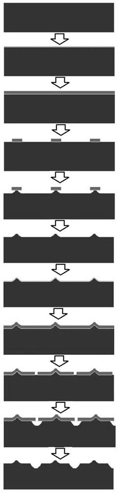
[0038]A preparation method of anti-glare glass, comprising the steps of:

[0039] S1, forming a patterned first photoresist layer on the structural surface of the cleaned glass substrate;

[0040] S2. Using the patterned first photoresist layer as a mask, etch the glass substrate to a given depth by first wet etching;

[0041] S3, cleaning the etched glass substrate, removing the first photoresist layer, and obtaining a glass substrate with a convex array on the structural surface;

[0042] S4. Clean the glass substrate obtained in step S3 again, and then form a patterned second pattern on the structural surface of the glass substrate by aligning the cross mark on the mask plate with the cross mark formed by the first wet etching of the glass substrate. photoresist layer;

[0043] S5. Using the patterned second photoresist layer as a mask, perform a second wet etching on the glass substrate to form an array of grooves (pits) on the structural surface of the glass substrate; ...

Embodiment 1

[0059] Raw material preparation:

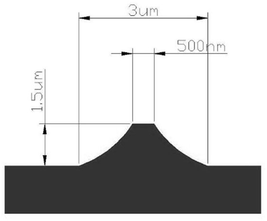
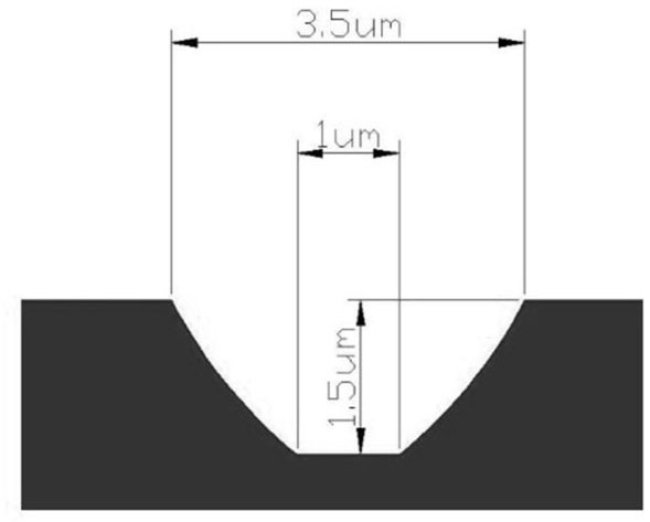
[0060] Make two masks, the 1# mask plate is a light-transmitting material plate, and a patterned structure is constructed on the light-transmitting material plate. The patterned structure is an array of chromium circles. The diameter of the chromium circles is 3 μm, and the distance between adjacent chromium circles is 12 μm. The 2# mask plate is a chromium mask plate, and a patterned light-transmitting structure is constructed on the chromium mask plate. The light-transmitting structure is an array of round holes, the diameter of the array round holes is 1 μm, and the distance between adjacent round holes is 12 μm.

[0061] Make cross alignment marks on the two mask boards respectively, and make a hollow cross in the middle of the square chromium block with alignment marks of 100μm×100μm. Make one in the middle of the left side and the right side, and make two mask alignment marks at the same position on the mask, so that when the 1# mask is...


PUM

PropertyMeasurementUnit
diameteraaaaaaaaaa
diameteraaaaaaaaaa

Abstract

The invention discloses a preparation method of anti-glare glass, comprising: S1, forming a patterned first photoresist layer on the structural surface of a glass substrate; S2, using the first photoresist layer as a mask, passing through the first photoresist layer Etching the glass substrate to a given depth by wet etching; S3, removing the first photoresist layer to obtain a glass substrate with a raised array on the structural surface; S4, forming a patterned second layer on the structural surface of the glass substrate Photoresist layer; S5, using the second photoresist layer as a mask, perform the second wet etching on the glass substrate to form an array of grooves on the structural surface of the glass substrate; S6, the second wet etched glass The substrate is cleaned, and the second photoresist layer is removed to obtain the anti-glare glass. The method is simple and controllable, has good process stability, and the prepared anti-glare glass has good microscopic flatness, high light transmittance, low reflectance, high gloss, stable performance parameters, and good performance equivalent to glass materials.

Description

technical field [0001] The invention belongs to the technical field of display screen glass, and in particular relates to a preparation method of anti-glare glass. Background technique [0002] Anti-glare glass is a special glass with low reflectivity and high transparency. Its English name is: Anti-glareglass. Viewing angle and brightness, reducing screen reflection, thus significantly improving the display effect. Anti-glare glass is mostly used in touch screens, display screens, touch panels, windows, etc. Products such as car navigation, instrumentation screens, mobile phones, computers, and advertising screens can all be applied to anti-glare glass. At present, the production of anti-glare glass is mainly based on two processes: making microstructures on the glass surface and coating the glass surface. The surface coating process often has a short service life due to the poor wear resistance of the coating itself. Therefore, more and more companies manufacture anti-gl...

Claims


Application Information

Patent Timeline
Patent Type & Authority Patents(China)
IPC IPC(8): C03C15/00C08J7/12G03F7/11G03F7/20G03F1/00C08L67/02C08L33/12C08L69/00
CPCC03C15/00C08J7/12C08J2333/12C08J2367/02C08J2369/00G03F1/00G03F7/11G03F7/2022
Inventor 胡云慧杨红斌刘印虢晓双隆祖亿彭传才
Owner 湖南天羿领航科技有限公司
Why Eureka
Try Eureka