Natural ventilation countercurrent type cooling tower air energy power generation device

A power generation device and natural ventilation technology, applied in wind power generation, installation/supporting configuration of wind turbines, water shower coolers, etc., can solve the problems of low cooling tower cooling efficiency, large cooling margin, etc., to improve antifreeze performance, The effect of reducing power consumption and reducing draft

Inactive Publication Date: 2019-09-17
高婧怡
View PDF0 Cites 3 Cited by
  • Summary
  • Abstract
  • Description
  • Claims
  • Application Information

AI Technical Summary

Problems solved by technology

[0003] The present invention aims at the problems of the large cooling margin of the natural ventilation counterflow cooling tower and the low cooling efficiency of the cooling tower due to anti-icing measures in winter, and provides an air energy power generation device using the natural ventilation counterflow cooling tower

Method used


Image

  • Natural ventilation countercurrent type cooling tower air energy power generation device
  • Natural ventilation countercurrent type cooling tower air energy power generation device
  • Natural ventilation countercurrent type cooling tower air energy power generation device

Examples


Embodiment 1

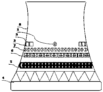
[0027] Embodiment 1 of the present invention: such as figure 1 with figure 2 As shown, this kind of natural ventilation counter-flow cooling tower air energy power generation device is provided with an air inlet system above the spray device 6 in the cooling tower, and the air inlets 1 of the four air inlet systems are arranged on the cooling tower barrel 8, which is Circumferentially symmetrically arranged. The air inlet pipe extends along the inspection channel in the tower to the inside of the tower tube, and the air inlet volume of each air inlet 1 is the same.

[0028] Install a wind generator 3 at the air inlet 1 of the air inlet pipe. The wind generator 3 preferably uses a breeze to start the generator and send power to the grid. As long as the air flow is used as power, the driving equipment of the wind generator 3 can be blades The fan can also be an axial fan or other forms, which does not affect the effect of this application; the total output power of the power gener...

Embodiment (2)

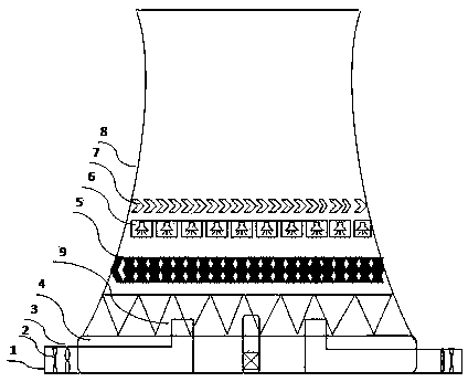
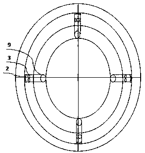
[0038] Embodiment (2) of the present invention: such as image 3 As shown, this kind of natural ventilation countercurrent cooling tower air energy power generation device is provided with an air inlet system above the spray device 6 in the cooling tower, and the air inlets 1 of the four air inlet systems are arranged outside the cooling tower, in a circumferential direction Symmetrically arranged, the air inlet pipe is arranged in the cooling tower pool 4 and extends to the central area of ​​the cooling tower, so that air can effectively enter the inside of the cooling tower barrel 8. This arrangement is used in the case of closing the cooling tower inner circle to spray water in winter. The air outside the tower enters into the tower tube 8 of the cooling tower smoothly, which reduces the air density inside the tower tube 8, increases the air outflow resistance, reduces the cooling tower's pumping force, and reduces the water spraying area from the lower part of the cooling to...


PUM


Abstract

The invention discloses a natural ventilation countercurrent type cooling tower air energy power generation device. The natural ventilation countercurrent type cooling tower air energy power generation device comprises an air inlet system and an air energy power generation device body. The power generation device is characterized in that air is directly introduced into a tower barrel of a cooling tower in winter or in a low-temperature environment, and due to the difference between the inner air density and the outer air density of the tower, the air outside the tower is accelerated to flow into the tower barrel, and power generated by air flowing is utilized for power generation. The power generation device has the beneficial effects that the air energy is utilized for power generation, so that the power generating capacity is increased; the suction force of the cooling tower is reduced, and the icing degree of the cooling tower in winter or in the low-temperature environment is improved; and the power consumption of a circulating cooling water system is reduced.

Description

Technical field [0001] The invention belongs to the fields of thermal power plants and nuclear power generation and renewable energy utilization, and relates to a natural ventilation countercurrent cooling tower air energy power generation device. Background technique [0002] Due to the difference in air density between the inside and outside of the tower, the natural ventilation counterflow cooling tower produces a pressure difference between the inside and outside of the tower, causing the air outside the tower to continuously flow into the tower without the need for ventilation machinery to provide power. It has high efficiency, low maintenance, Features such as low operating costs. The natural draft counterflow cooling tower is currently one of the most widely used and important cooling equipment in thermal power plants and nuclear power plants. Since the cooling capacity of the circulating water system and the cooling tower is designed to meet the condenser vacuum requirem...

Claims


Application Information

Patent Timeline
Patent Type & Authority Applications(China)
IPC IPC(8): F03D9/35F03D80/00F03D9/25F03D13/20F28C1/02
CPCF03D9/25F03D9/35F03D13/20F03D80/00F28C1/02Y02E10/72Y02E10/728Y02P80/10
Inventor 高婧怡高国庆高怡红
Owner 高婧怡
Why Eureka
Try Eureka