Large-field splicing exposure machine

A spliced, large field of view technology, applied in optomechanical equipment, microlithography exposure equipment, photolithography process exposure devices, etc., can solve the problem of increasing the cost of the lighting system, proportionally increasing the size of the unit pixel, and reducing the projection area. minor issues

Pending Publication Date: 2019-09-17
联士光电(深圳)有限公司
View PDF0 Cites 7 Cited by
  • Summary
  • Abstract
  • Description
  • Claims
  • Application Information

AI Technical Summary

Problems solved by technology

The two requirements of large format and high precision are mutually restrictive. If the requirement of high precision is met, the magnification of the imaging lens needs to be reduced, resulting in a reduction in the projection format, which cannot meet the needs of industrial production. If the projection format is further increased, it is necessary to Increase the magnification o

Method used


Image

  • Large-field splicing exposure machine
  • Large-field splicing exposure machine
  • Large-field splicing exposure machine

Examples


Embodiment Construction

[0010] specific implementation plan

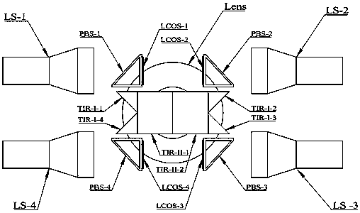
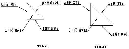
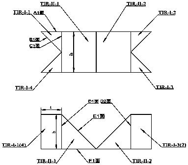
[0011] The system consists of an imaging lens Lens, four pieces of silicon-based liquid crystals of the same specification, namely LCOS-1, LCOS-2, LCOS-3 and LCOS-4, and four pieces of polarization beam splitters, namely PBS-1, PBS-2, PBS-3 And PBS-4, four I-type right-angle triangular total reflection prisms TIR-I-1, TIR-I-2, TIR-I-3 and TIR-I-4 with the same specifications, two II-type right-angle triangles with the same specifications Composed of total reflection prisms TIR-II-1 and TIR-II-2, four light sources LS-1, LS-2, LS-3 and LS-4.

[0012] The overall system structure is attached figure 1 As shown, light sources LS-1, LS-2, LS-3 and LS-4 pass through PBS-1, PBS-2, PBS-3 and PBS-4 respectively to LCOS-1, LCOS-2, LCOS-3, LCOS -4 independent lighting, LCOS-1, LCOS-2, LCOS-3 and LCOS-4 combined with PBS-1, PBS-2, PBS-3 and PBS-4 respectively, the angle between PBS and LCOS photosensitive surface is 45° , PBS-1, PBS-2, PBS-3 and PB...


PUM


Abstract

The invention provides an optical system of a large-field splicing exposure machine. The system is characterized in that a digital graph output by a signal source is transversely and longitudinally segmented, images of each sub-field are respectively transmitted to four LCOS (Liquid Crystal on Silicon) systems with the same specification, and each LCOS is spliced into an image which is the same as the original field after passing through a polarization beam splitter and two total reflection prisms, namely the total resolution is expanded to be four times of that of the original chip. The system can effectively solve the problem that the field of a traditional exposure machine is limited by the size of the chip and large-amplitude exposure cannot be performed.

Description

technical field [0001] The invention relates to a large field of view splicing exposure machine. Background technique [0002] Large-format high-precision is the development trend of exposure machines. If you want to meet the high-precision requirements, you need to reduce the chip pixel size. If you want to meet the large-format requirements, you need to increase the number of chip pixels, that is, increase the resolution. However, due to the constraints of the existing chip technology level, the indicators of the two parameters are limited, and any breakthrough in the indicators will lead to a substantial increase in cost, and it takes a long period from the development of new products to product finalization. For example, the current LCOS (Liquid Crystal on Silicon, that is, liquid crystal on silicon, which is a very small matrix liquid crystal display device based on reflection mode) chip has the highest resolution of 4096x2400, that is, 4k chip. The two requirements of...

Claims


Application Information

Patent Timeline
IPC IPC(8): G03F7/20
CPCG03F7/70116G03F7/70191G03F7/70475
Inventor 孙雷张洪波张婧姣
Owner 联士光电(深圳)有限公司
Why Eureka
Try Eureka