Battery cover plate structure based on nano injection molding and preparation method thereof

A battery cover, nano-injection technology, applied in battery cover/end cover, battery, nanotechnology and other directions, can solve the problem of low pass rate of battery cover, and achieve the effect of improving pass rate and reducing cost

Pending Publication Date: 2019-09-17
池州市骏智机电科技有限公司
View PDF0 Cites 2 Cited by
  • Summary
  • Abstract
  • Description
  • Claims
  • Application Information

AI Technical Summary

Problems solved by technology

[0004] The purpose of the present invention is to provide a nano-injection-based battery cover structure and its preparation method to solve the problem of low pass rate of battery cover

Method used


Image

  • Battery cover plate structure based on nano injection molding and preparation method thereof
  • Battery cover plate structure based on nano injection molding and preparation method thereof
  • Battery cover plate structure based on nano injection molding and preparation method thereof

Examples


Embodiment 1

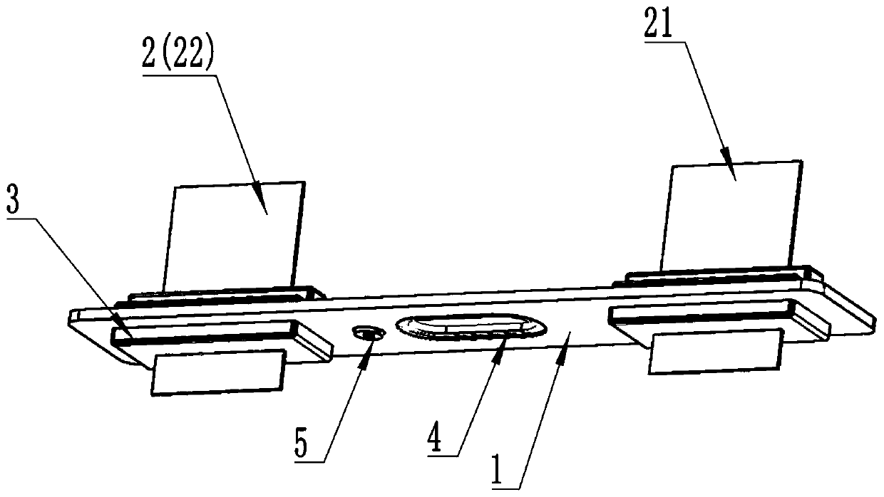
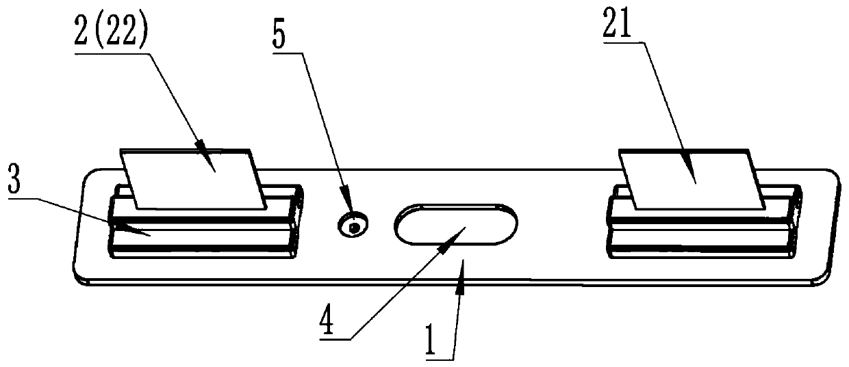
[0033] Please refer to figure 1 , this embodiment 1 provides a battery cover plate structure based on nano-injection molding.

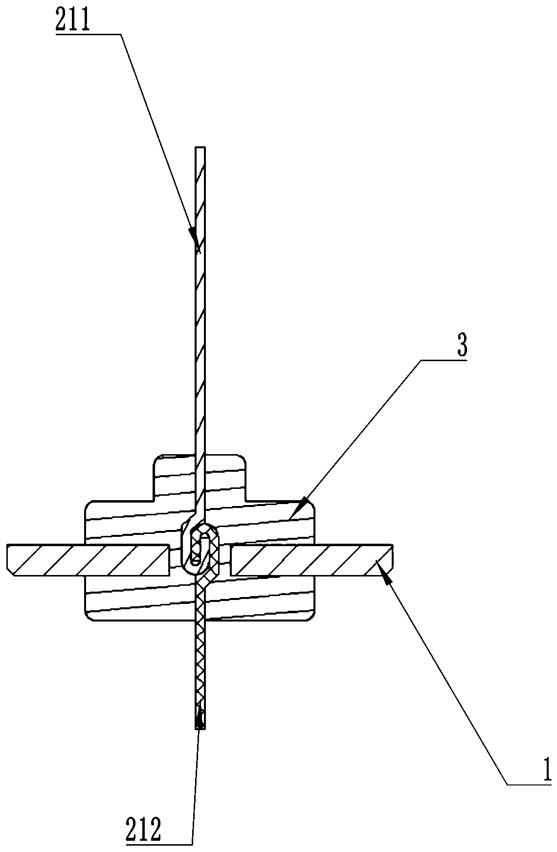
[0034] The battery cover plate structure includes a cover plate 1 and a connecting piece 2, and a plurality of nanopores are opened on the surface of the connecting piece 2 and the surface of the cover plate 1 facing the connecting piece 2; the cover plate 1 and the connecting piece 2 are fixedly connected by an injection molded part 3, and the injection molded part 3 penetrates into the nanopore.

[0035] After the airtightness test, it was found that the airtightness test leakage rate of the battery cover plate structure was less than 10 -7 (Pa·m 3 ) / s. The equipment used in the air tightness test is a helium detector provided by Anhui Wanyi Technology Co., Ltd. The specific process and parameters are as follows:

[0036] Place the battery cover structure in a sealed jig, and draw the internal vacuum through a vacuum pump (set time 15s, end at 3...

Embodiment 2

[0049] This embodiment 2 provides a method for preparing a battery cover structure based on nano-injection molding, and the battery cover structure in embodiment 1 can be obtained.

[0050] The preparation method comprises the following steps:

[0051] S1. Open a plurality of nanopores on the surface of the connecting sheet 2 and the surface of the cover plate 1 facing the connecting sheet 2;

[0052] S2. Insert the connecting sheet 2 with nanopores on the surface into the battery cover plate 1;

[0053] S3. Injecting plastic at the joint between the connecting piece 2 and the battery cover 1 to form an injection molded part 3, so that the connecting piece 2 and the battery cover 1 are fixedly connected.

[0054] Among them, the size and distribution density of the nanopores, the material of the injection molding plastic, etc. are all introduced in detail in Example 1, and will not be repeated here.

[0055] The opening of the nanopores in step S1 is carried out by chemical ...

Embodiment 3

[0069] Example 3 provides a lithium ion battery, including the battery cover structure described in Example 1 and the battery cover structure prepared by the preparation method in Example 2.


PUM

PropertyMeasurementUnit
Apertureaaaaaaaaaa
Hole depthaaaaaaaaaa

Abstract

The invention discloses a battery cover plate structure based on nano injection molding and a preparation method thereof. The battery cover plate structure comprises a cover plate and a connecting sheet, and the surface of the connecting sheet and the surface, facing the connecting sheet, of the cover plate are provided with a plurality of nano holes. The cover plate and the connecting sheet are fixedly connected through an injection molding part, and the injection molding part penetrates into the nano holes. According to the invention, the injection molding plastic can permeate into the nano holes, so the binding force between the connecting sheet and the cover plate is improved, and the good air tightness of the joint of the connecting sheet and the cover plate is ensured. Compared with the prior art, the lower plastic part and the sealing ring are reduced, the qualification rate of finished products can be improved, and the cost is reduced. Furthermore, in the traditional technology, if the connecting sheet is of a composite structure and needs to be subjected to friction welding machining, the binding force can be improved through injection molding of plastic by use of an existing composite structure, friction welding is not needed any more, cost is reduced, and the fracture risk of the connecting sheet can be completely avoided.

Description

technical field [0001] The invention relates to the field of batteries, in particular to a nano-injection-based battery cover structure and a preparation method thereof. Background technique [0002] At present, in the battery cover structure of the power battery in the new energy automobile industry, the connecting piece and the cover plate generally adopt the assembly process. Specifically, friction welding is performed on the positive / negative electrode connecting piece according to the requirements. The friction welding process is mainly used when the connecting piece is a composite structure, such as copper and aluminum sheets are formed by friction welding to form a copper-aluminum composite connecting piece. Then the sealing ring made of fluororubber and the lower plastic part formed by injection molding of PP material are assembled on the positive / negative electrode connecting piece; the aluminum cover plate formed by stamping is assembled on the sealing ring and the...

Claims


Application Information

Patent Timeline
IPC IPC(8): H01M2/04H01M2/26H01M2/08H01M10/0525B82Y40/00H01M50/147H01M50/172H01M50/543H01M50/55
CPCH01M10/0525B82Y40/00H01M2220/20H01M50/147H01M50/183H01M50/531Y02E60/10
Inventor 李新宏钟军陈洪亮邓银桥陈圣周斌
Owner 池州市骏智机电科技有限公司
Why Eureka
Try Eureka