Supercharge Your Innovation With Domain-Expert AI Agents!

Method for automatically adjusting anode pressure intensity and flow rate of fuel cell with circulation pump

A fuel cell and circulation pump technology, applied in fuel cells, power system fuel cells, circuits, etc., can solve problems such as rising anode pressure of the stack, reducing battery output efficiency, and destroying membrane electrodes, so as to achieve the effect of maintaining stable operation

Active Publication Date: 2019-09-17
BEIJING INSTITUTE OF TECHNOLOGYGY
View PDF2 Cites 3 Cited by
  • Summary
  • Abstract
  • Description
  • Claims
  • Application Information

AI Technical Summary

Problems solved by technology

When the hydrogen supplied by the hydrogen supply system is excessive, although the fuel cell reacts fully, the power consumed by the hydrogen circulation pump increases, reducing the output efficiency of the battery
At the same time, too much hydrogen will increase the pressure of the anode of the stack, resulting in an increase in the pressure difference between the cathode and the anode, which will affect the life of the proton exchange membrane; when the hydrogen supplied by the hydrogen supply system is not enough for the hydrogen required by the fuel cell, the fuel cell will The phenomenon of "fuel starvation" will result in a reduction in the life of the fuel cell, and in severe cases, the membrane electrode will even be damaged and the fuel cell will be scrapped

Method used


Image

  • Method for automatically adjusting anode pressure intensity and flow rate of fuel cell with circulation pump
  • Method for automatically adjusting anode pressure intensity and flow rate of fuel cell with circulation pump
  • Method for automatically adjusting anode pressure intensity and flow rate of fuel cell with circulation pump

Examples


Embodiment Construction

[0032] Specific embodiments of the present invention will be described in detail below in conjunction with the accompanying drawings.

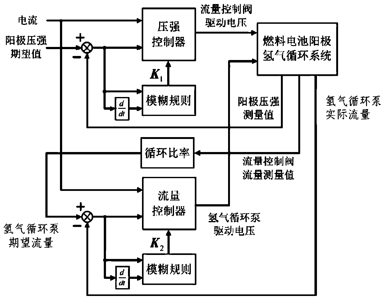
[0033] Such as figure 1 As shown, the fuel cell hydrogen supply system proposed by the present invention includes a high-pressure hydrogen storage tank, a flow control valve 1, a gas supply manifold 2, a return manifold 3, a hydrogen circulation pump 4, a hydrogen exhaust valve 5 and a fuel cell anode flow channel, The schematic diagram of the overall structure of the hydrogen supply system is as follows: figure 1 shown.

[0034] The flow control valve controls the flow of hydrogen gas flowing from the high-pressure hydrogen storage tank into the gas supply manifold;

[0035] One end of the gas supply manifold is connected to the flow control valve and the output of the hydrogen circulation pump, and the other end of the gas supply manifold is connected to the anode flow channel of the fuel cell. The gas flowing into the gas supply manifold...


PUM


Abstract

The invention relates to a method for automatically adjusting the anode pressure intensity and flow rate of a fuel cell with a circulation pump to realize the automatic adjustment of the anode hydrogen pressure intensity and flow rate of the fuel cell. A fuel cell anode hydrogen supply system is composed of a high-pressure hydrogen tank, a flow control valve, a hydrogen supply manifold, a return manifold, a hydrogen circulation pump, a pressure intensity controller and a flow controller, wherein the pressure intensity controller controls the driving voltage of the flow control valve so as to control the output flow of the flow control valve in order to further adjust the anode pressure intensity of the fuel cell. A fuel cell current value, an anode pressure intensity measured value and an anode pressure intensity expected value are input into the pressure intensity controller, and a flow control valve control voltage is output from the pressure intensity controller. The flow controller controls the driving voltage of the hydrogen circulation pump to adjust the output flow of the hydrogen circulation pump. The fuel cell current value, a hydrogen circulation pump actual flow rate, and a hydrogen circulation pump desired flow rate are input into the flow controller, and a hydrogen circulation pump driving voltage is output from the flow controller.

Description

technical field [0001] The invention relates to a fuel cell auxiliary system, in particular to a fuel cell anode hydrogen supply system. Background technique [0002] Fuel cells convert chemical energy into electrical energy through electrochemical reactions, and use fuel and oxygen as raw materials, and have no mechanical transmission parts, so they have the advantages of high efficiency, no noise, and no pollution. From the perspective of saving energy and protecting the ecological environment, fuel cells are the most promising power generation technology. Today, proton exchange membrane fuel cell power generation as a new generation of power generation technology, its application prospects are very broad, and as a vehicle power research has made substantial progress. As the fuel of the fuel cell, hydrogen is stored in the on-board hydrogen storage bottle, and is introduced into the anode of the battery stack through the gas supply device for electrochemical reaction. Co...

Claims


Application Information

Patent Timeline
Patent Type & Authority Applications(China)
IPC IPC(8): H01M8/04089H01M8/04746
CPCH01M8/04097H01M8/04104H01M8/04753H01M2250/20Y02E60/50
Inventor 何洪文王亚雄权盛伟
Owner BEIJING INSTITUTE OF TECHNOLOGYGY
Features
  • R&D
  • Intellectual Property
  • Life Sciences
  • Materials
  • Tech Scout
  • Unparalleled Data Quality
  • Higher Quality Content
  • 60% Fewer Hallucinations
Learn More