
Split-flow filtration type gas-liquid-solid three-phase cyclone separation apparatus

A technology of cyclone separation device and filter device, which is applied in the direction of separation method, sediment separation by centrifugal force, liquid degassing, etc. It can solve the problems of slow bubble precipitation and impurity sedimentation rate, influence of oil flow state, low cleaning efficiency, etc. , to achieve the effect of ensuring excellent quality, broadening the application field and improving separation performance

Active Publication Date: 2019-09-20
YANSHAN UNIV
View PDF10 Cites 2 Cited by
  • Summary
  • Abstract
  • Description
  • Claims
  • Application Information

AI Technical Summary

Problems solved by technology

Moreover, at present, the separation of air bubbles and impurities is mostly carried out separately, and the separation efficiency is low and the effect is limited.
The natural precipitation method is suitable for large-volume oil tanks. The precipitation of air bubbles and the sedimentation of impurities are slow, and the cleaning efficiency of the oil in the flowing state is low; directly installing a filter at the oil return port can effectively ensure the cleanliness of the oil, which is convenient and quick, but due to the natural In the oil return state, there is a pressure loss in the oil passing through the filter, and the flow rate slows down, which has a great impact on the oil flow state

Method used


Image

  • Split-flow filtration type gas-liquid-solid three-phase cyclone separation apparatus
  • Split-flow filtration type gas-liquid-solid three-phase cyclone separation apparatus
  • Split-flow filtration type gas-liquid-solid three-phase cyclone separation apparatus

Examples


Embodiment Construction

[0026] In order to make the purpose, technical solutions and advantages of the embodiments of the present invention clearer, the technical solutions in the embodiments of the present invention will be clearly and completely described below in conjunction with the drawings in the embodiments of the present invention. Obviously, the described embodiments It is a part of embodiments of the present invention, but not all embodiments.

[0027] In describing the present invention, it is to be understood that the terms "radial", "axial", "upper", "lower", "top", "bottom", "inner", "outer" etc. indicate orientation Or the positional relationship is based on the orientation or positional relationship shown in the drawings, which is only for the convenience of describing the present invention and simplifying the description, and does not indicate or imply that the referred device or element must have a specific orientation, be constructed and operated in a specific orientation , and the...


PUM


Abstract

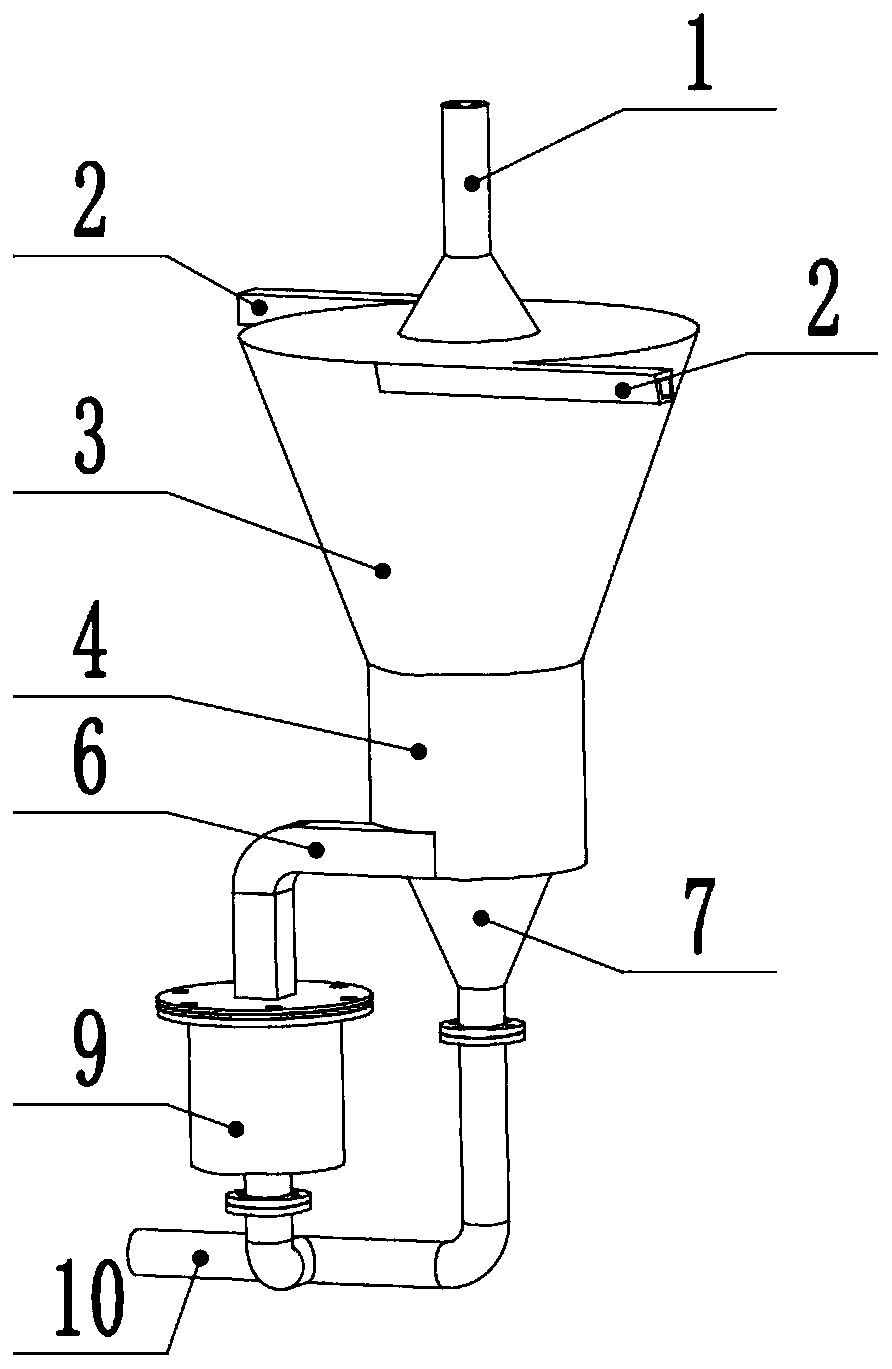
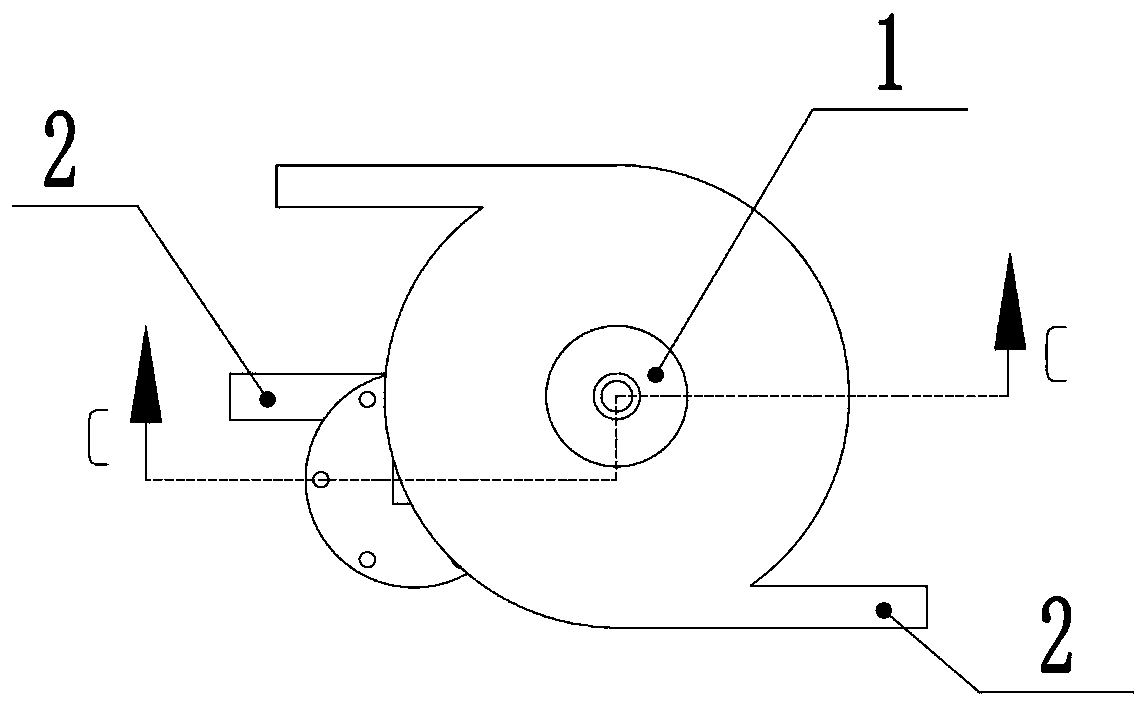
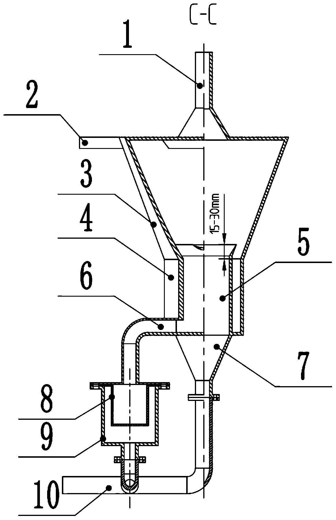
The invention discloses a split-flow filtration type gas-liquid-solid three-phase cyclone separation apparatus, and is applied in the field of hydraulic fluid cleaning. The apparatus comprises a swirling barrel, an exhaust pipe installed on the top of the barrel, inflow pipes tangential to the upper wall of the barrel, a split-flow baffle plate inside the barrel, a lateral outflow pipe tangential to the lower wall of the barrel, a filtering apparatus with a filtering net arranged inside the filtering apparatus, and connected with the lateral outflow pipe, a funnel-shaped vertical outflow port communicating with the inside of the split-flow baffle plate, and a confluence pipeline. The apparatus firstly uses swirling centrifugal force to realize boundary aggregation of contamination impurities and formation of a gas core center, then separation of boundary impurity oil is completed by the split-flow baffle plate, and at the same time a high-speed swirling state required for bubble elimination is maintained, so that oil filtration is completed, bubble elimination is ensured, and three-phase synchronous efficient separation is realized. At the same time, the boundary contamination oil after filtration participates in the system oil circulation, and thus stability of a system flow is ensured. The apparatus structure is simple, separation is efficient, the equipment manufacturing cost is low, and application ranges are wide.

Description

technical field [0001] The invention relates to the field of hydraulic oil cleaning, in particular to a split-flow filter type gas-liquid-solid three-phase cyclone separation device. Background technique [0002] During the operation of the hydraulic system, due to the suction of the hydraulic pump or the high-speed jet flow at the valve port, a certain amount of gas will be mixed into the oil, causing cavitation of components, vibration and noise of the hydraulic system, and crawling of the hydraulic cylinder; at the same time, due to Due to the wear of hydraulic components and the intrusion of pollutants, the oil will be polluted by impurities, which will cause damage to the hydraulic components and reduce the service life. [0003] At present, the methods used to remove air bubbles and impurities in hydraulic oil are mainly divided into natural precipitation and sedimentation methods, filtration methods, etc. Moreover, at present, the separation of air bubbles and impuri...

Claims


Application Information

Patent Timeline
Patent Type & Authority Applications(China)
IPC IPC(8): B01D19/00B01D21/26
CPCB01D19/0057B01D21/26
Inventor 张晋吕瑞琪杨起帆柳宝磊
Owner YANSHAN UNIV
Learn More