Integrated micro-channel heat dissipation structure, preparation method and wafer-level packaging structure

A heat-dissipating structure and micro-channel technology, applied in micro-structure devices, manufacturing micro-structure devices, micro-structure technology, etc., can solve the problem of unsatisfactory chip heat dissipation effect, achieve super-large heat-dissipation capacity, ultra-high integration, and solve heat-dissipation problems. effect of the problem

Inactive Publication Date: 2019-09-20
CHINA ELECTRONIC TECH GRP CORP NO 38 RES INST
View PDF9 Cites 11 Cited by
  • Summary
  • Abstract
  • Description
  • Claims
  • Application Information

AI Technical Summary

Problems solved by technology

[0006] The technical problem to be solved by the present invention is: the heat dissipation effect of the chip in the prior art is not ideal

Method used


Image

  • Integrated micro-channel heat dissipation structure, preparation method and wafer-level packaging structure
  • Integrated micro-channel heat dissipation structure, preparation method and wafer-level packaging structure
  • Integrated micro-channel heat dissipation structure, preparation method and wafer-level packaging structure

Examples


Embodiment 1

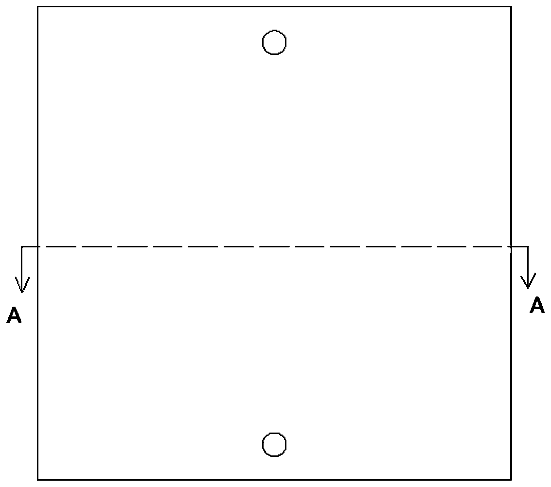
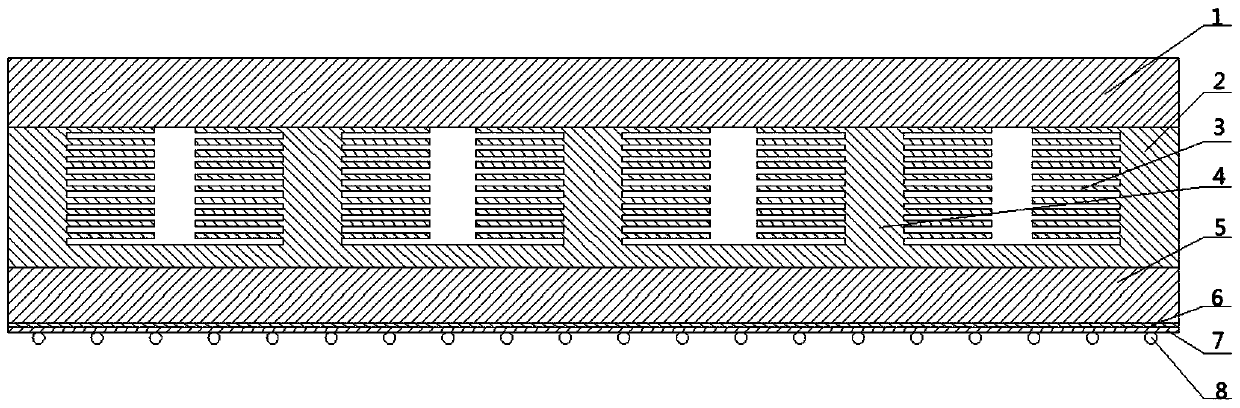
[0038] Such as figure 1 , figure 2 As shown, in this embodiment, the integrated microchannel heat dissipation structure includes a first cover plate 1, a second cover plate 2, primary fins 3, and secondary fins 4;

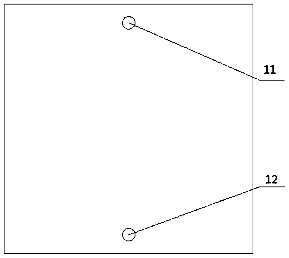
[0039] The first cover plate 1 and the second cover plate 2 form a housing with a cavity, and a plurality of primary fins 3 arranged in parallel at intervals are arranged in the cavity. The inner side is provided with secondary fins 4, and the secondary fins 4 are a plurality of sheet-like heat sinks arranged at intervals, and the heat dissipation surface formed is dozens of times that of the chip itself, and the top surface of the shell is provided with a liquid inlet hole for the cooling medium to enter 11 and a liquid outlet 12 through which the cooling medium flows out. The heat exchange channels are formed by the gaps between the primary fins 3 and the gaps between the secondary fins 4 .

[0040] to combine image 3 , Figure 4 , Figure 5 As shown, the...

Embodiment 2

[0044] Such as Figure 5 , Figure 6 As shown, the two sides of the inner bottom surface of the second cover plate 2 are respectively provided with a distribution groove 21 and a confluence groove 22 corresponding to the liquid inlet 11 and the liquid outlet 12, and the distribution groove 21 passes between the adjacent primary fins 3 The space between the secondary fins 4 and the space between the secondary fins 4 communicate with the flow groove 22. The distributing groove 21 can realize that the liquid is stored in the distributing groove 21 first, and then flows to the confluence groove 22 respectively through the gaps between the adjacent primary fins 3 and the gaps between the secondary fins 4, so as to realize the uniformity of the cooling medium. distribute.

[0045] The present invention also provides a method for preparing a wafer-level packaging structure with an integrated microchannel heat dissipation structure, comprising the following steps:

[0046] SO1: Pre...


PUM


Abstract

The invention discloses an integrated micro-channel heat dissipation structure. The heat dissipation structure comprises a shell with a cavity, a plurality of first-stage fins which are arranged in parallel at intervals are arranged in the cavity, second-stage fins are arranged on the two sides of the first-stage fins and the inner side of the shell, the second-stage fins are formed by arranging a plurality of sheet-shaped cooling fins at intervals, and a liquid inlet for a cooling medium to enter and a liquid outlet for the cooling medium to flow out are formed in the top surface of the shell. The invention further discloses a preparation method of the integrated micro-channel heat dissipation structure and a wafer-level packaging structure adopting the integrated micro-channel heat dissipation structure. The heat dissipation structure has the advantages that the heat exchanger is provided with two stages of heat exchange fins, and the heat exchange area is dozens of times of the chip contact area; the heat dissipation structures are both made of silicon materials and are connected in a silicon-silicon bonding mode, due to the fact that only hundreds of micrometers of silicon materials exist between the refrigeration working medium and the heat source, the thermal resistance between the refrigeration working medium and the heat source can be reduced to the limit, the heat dissipation problem of the high-power chip is solved, and thermal mismatch of heterogeneous materials does not exist.

Description

technical field [0001] The invention relates to a chip field, in particular to an integrated microfluidic cooling structure, a preparation method and a wafer-level packaging structure. Background technique [0002] With the rapid development of semiconductor technology, transistor density continues to increase, chip performance continues to improve, and chip power and heat flux density are increasing. Chip heat dissipation capability has become a key factor restricting the further development of Moore's Law. The traditional heat dissipation method uses liquid cooling or air cooling to dissipate heat for the packaged chip through a heat sink. The heat conduction of the functional layer on the surface of the chip needs to go through a large number of intermediate thermal resistances such as the chip substrate, chip package, thermal conductive silicone grease, and heat sink. It reaches the cooling medium, and because of the integration of various heterogeneous materials, it is ...

Claims


Application Information

Patent Timeline
Patent Type & Authority Applications(China)
IPC IPC(8): B81B7/00B81C1/00H01L21/48H01L23/473
CPCB81B7/0093B81C1/00119H01L21/4882H01L23/473
Inventor 王志海盛文军周金文邵世东毛亮
Owner CHINA ELECTRONIC TECH GRP CORP NO 38 RES INST
Why Eureka
Try Eureka