
Control method for carbonization system in biomass external thermal method thermal carbon co-production system

A carbonization system and control method technology, which is applied in the fields of biofuel, gasification process, manufacture of combustible gas, etc., can solve the problems of low conversion rate, low energy efficiency, lack of energy, etc., achieve high carbonization degree, improve carbonization efficiency, and optimize carbonization efficiency. Effect

Active Publication Date: 2019-09-20
青岛德瑞汇丰环保科技股份有限公司
View PDF10 Cites 2 Cited by
  • Summary
  • Abstract
  • Description
  • Claims
  • Application Information

AI Technical Summary

Problems solved by technology

[0004] However, when the prior art carbonizes agricultural waste, the conversion rate of carbonization is relatively low, and the energy efficiency ratio is low, which seriously affects and restricts the utilization of agricultural waste. The prior art has made many improvements to the carbonization device, but it lacks through Method of improving carbonization efficiency by controlling carbonization reactor time

Method used


Image

  • Control method for carbonization system in biomass external thermal method thermal carbon co-production system
  • Control method for carbonization system in biomass external thermal method thermal carbon co-production system
  • Control method for carbonization system in biomass external thermal method thermal carbon co-production system

Examples


Embodiment Construction

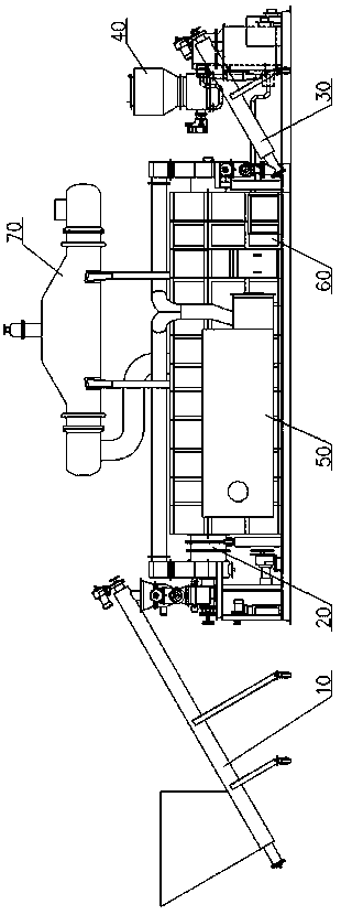
[0037] The following describes a thermal charcoal cogeneration system with external heat from biomass in conjunction with the accompanying drawings.

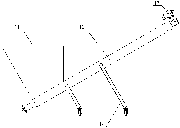
[0038] Such as figure 1 and 2 As shown, the thermal carbon cogeneration system of biomass external heat method includes a feed system 10, a carbonization system 20, a discharge system 30, a biomass gasification system 40, a waste gas incineration system 50, an external heat system 60, and a steam generation system 70. The material outlet of the feeding system 10 is connected to the carbonization system 20, the waste material outlet of the carbonization system 20 is connected to the discharge system 30, the flue gas outlet of the carbonization system 20 is connected to the flue gas inlet of the waste gas incineration system 50, and the The flue gas outlet of the exhaust gas incineration system 50 and the gas outlet of the biomass gasification system 40 are connected to the external heating system 60 , and the flue gas outlet of ...


PUM


Abstract

The invention relates to a control method for a carbonization system of a biomass external thermal method thermal carbon co-production system, wherein the carbonization system comprises a feeding mechanism, a material preparing mechanism, a carbonization reactor, a gas discharge pipeline a, a gas discharge pipeline b and a material collecting mechanism, the residence time of a material in the carbonization reactor is determined by the average particle size and the water content of the material, and the correlation is described by the following equation: t=a*m*e<d / m>+b, wherein t represents the residence time of the material in the reactor, a represents a material particle size correlation constant and is 52.131, b represents a material water content correlation constant and is 15.260, e represents a natural constant and is 2.718, d represents a material average particle size, is more than or equal to 0.003 and is less than or equal to 0.05, and has the unit of m, and m represents a material dry group water content, and is more than or equal to 5% and is less than or equal to 80%. According to the present invention, by controlling the residence time of the material in the carbonization system, the carbonization degree of the material can be controlled efficiently, the heating is performed for the optimal time, the minimal heat energy is consumed, the optimal carbonization effect is generated, the carbonization efficiency ratio is optimal, and the conveniently-used environmentally friendly flue gas is produced so as to improve the carbonization efficiency of the material.

Description

technical field [0001] The invention belongs to the technical field of comprehensive utilization of agricultural biomass waste, and specifically relates to a control method for a carbonization system in a thermal carbon cogeneration system of a biomass external heat method. Background technique [0002] In recent years, my country's agriculture has continued to develop steadily, and the level of large-scale farming has been significantly improved, ensuring the supply of meat, eggs and milk. However, a large amount of agricultural waste has not been effectively treated and utilized, which has become a major problem in rural environmental governance. Doing a good job in the resource utilization of agricultural waste is related to the effective supply of agricultural products and the improvement of the production and living environment of rural residents. It is a major livelihood project. [0003] At present, the market mainly uses biogas engineering and composting for the reso...

Claims


Application Information

Patent Timeline
Patent Type & Authority Applications(China)
IPC IPC(8): C10B53/02C10B47/44C10B57/00C10J3/64C10J3/72C10J3/80C10J3/84
CPCC10B47/44C10B53/02C10B57/00C10J3/64C10J3/72C10J3/723C10J3/725C10J3/80C10J3/84C10J2200/152C10J2300/0909C10J2300/0916C10J2300/1223Y02E50/10
Inventor 张瑞亮
Owner 青岛德瑞汇丰环保科技股份有限公司
Learn More