A visual test bench for performance testing of hydraulic valves
A technology of experimental bench and hydraulic valve, which is applied in fluid pressure actuation system test, fluid pressure actuation device, mechanical equipment, etc. It can solve the problem of not being able to effectively grasp the flow field of the valve channel and the uncontrollable pressure and flow conditions of the experimental valve, etc. Problems, to achieve accurate and more comprehensive experimental values, high light transmittance, and improve the effect of safety
- Summary
- Abstract
- Description
- Claims
- Application Information
AI Technical Summary
Problems solved by technology
Method used
Image

Examples
specific Embodiment approach 1
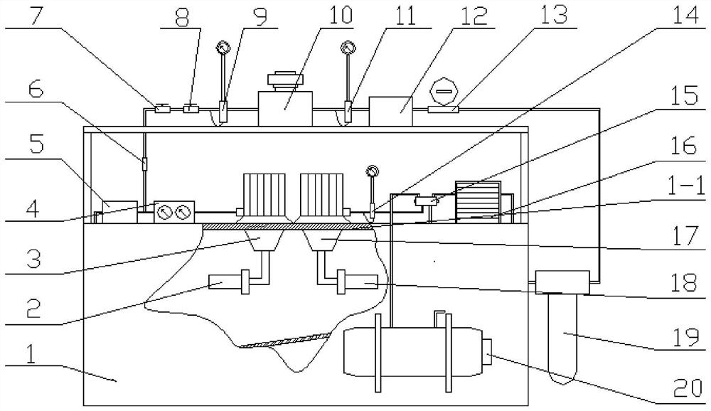
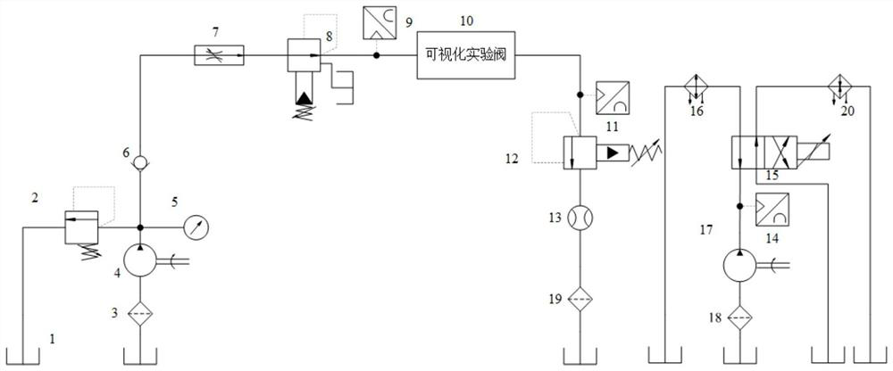
[0015] Specific implementation mode one: refer to figure 1 and figure 2 Specifically explain this embodiment, a visual test bench for hydraulic valve performance detection described in this embodiment, which includes a fuel tank 1, a hydraulic pump 3, a pressure gauge 4, a speed control valve 7, a pilot fixed value Pressure valve 8, No. 1 pressure sensor 9, visualization experiment valve 10, No. 2 pressure sensor 11, pilot relief valve 12, flow sensor 13, temperature sensor 14, electromagnetic reversing valve 15, cooler 16, No. 2 hydraulic pump 17 and heater 20;
[0016] The inside of the fuel tank 1 is fixedly connected with a horizontal partition 1-1, and the horizontal partition 1-1 divides the fuel tank 1 into two cavities, the lower cavity is used to load fuel oil, the upper cavity is used to place experimental instruments, and the upper cavity The cavity wall of the body is made of transparent material;
[0017] The electromagnetic reversing valve 15 is provided with...
specific Embodiment approach 2
[0020] Specific embodiment 2: This embodiment is to further limit the visualization test bench for hydraulic valve performance detection described in specific embodiment 1. In this embodiment, the test bench also includes No. 1 filter 2 and No. 2 filter 18, No. 1 filter 2 is installed on the oil suction end of No. 1 hydraulic pump 3, and No. 2 filter 18 is installed on the oil suction end of No. 2 hydraulic pump 17. Other compositions and connection methods are the same as those in Embodiment 1.
[0021] In this way, the No. 1 filter 2 and No. 2 filter 18 are mainly used to filter the hydraulic oil, so as to prevent some impurities in the hydraulic oil from entering the experimental pipeline under the action of the hydraulic pump and cause damage to some experimental instruments, reducing the test bench. service life.
specific Embodiment approach 3
[0022] Specific embodiment three: this embodiment is to further limit the visualization test bench for performance detection of hydraulic valves described in specific embodiment one. In this embodiment, the test bench also includes a direct-acting relief valve 5. The direct-acting overflow valve 5 is fixedly connected to the horizontal partition 1-1, and the direct-acting overflow valve 5 is set between the speed control valve 7 and the pressure gauge 4. The input of the direct-acting overflow valve 5 The end is connected with the output end of the pressure gauge 4 through the oil pipe, and the output end of the direct-acting overflow valve 5 is connected with the lower cavity of the fuel tank 1 . Other compositions and connection methods are the same as those in Embodiment 1.
[0023] With this setting, the operator can properly adjust the outlet pressure of the No. 1 hydraulic pump 3 through the direct-acting relief valve 5, so as to avoid the impact damage to the test bench...
PUM
 Abstract
Description
Claims
Application Information
 - R&D
- Intellectual Property
- Life Sciences
- Materials
- Tech Scout
- Unparalleled Data Quality
- Higher Quality Content
- 60% Fewer Hallucinations
Browse by: Latest US Patents, China's latest patents, Technical Efficacy Thesaurus, Application Domain, Technology Topic, Popular Technical Reports.
© 2025 PatSnap. All rights reserved.Legal|Privacy policy|Modern Slavery Act Transparency Statement|Sitemap|About US| Contact US: help@patsnap.com