Sampling machine

A sampling machine and sampling head technology, applied in the field of sampling machines, can solve the problems of poor stability, complex structure, difficult adaptation of alloy materials, etc., and achieve the effects of flattening the sampled part, easy welding and repairing, and good stability

Pending Publication Date: 2019-09-20
国能神福(晋江)热电有限公司 +2
View PDF0 Cites 0 Cited by
  • Summary
  • Abstract
  • Description
  • Claims
  • Application Information

AI Technical Summary

Problems solved by technology

[0006] Existing micro-damage sampling devices mainly use pneumatic cutting, electric spark cutting, and spherical or semi-spherical milling cutter cutting; however, these sampling devices generally have complex structures, poor stability, and insufficient strength of arc-shaped cutters. The operation is inconvenient, the surface of the sampled part is uneven, and it needs to be polished again, and the workload is large; especially for some high-hardness alloy materials, it is difficult to adapt

Method used


Image

  • Sampling machine
  • Sampling machine
  • Sampling machine

Examples


Embodiment 1

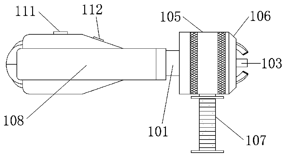
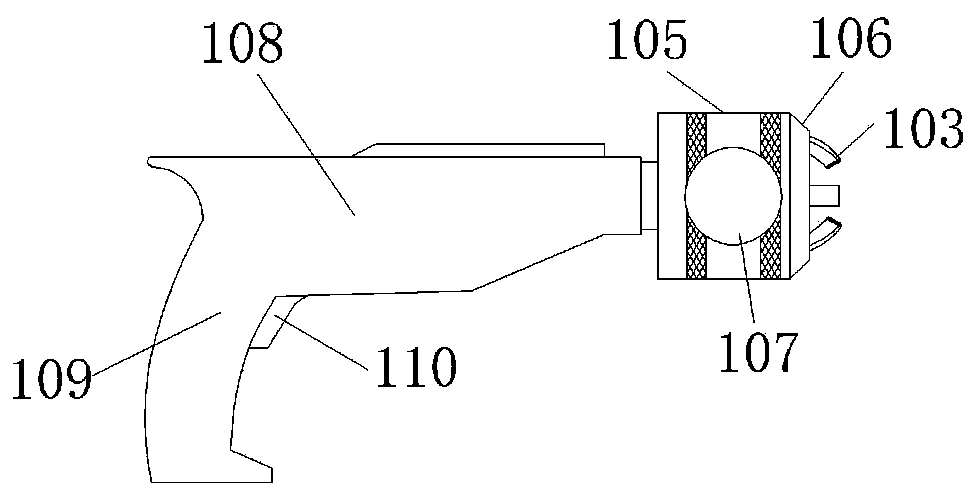
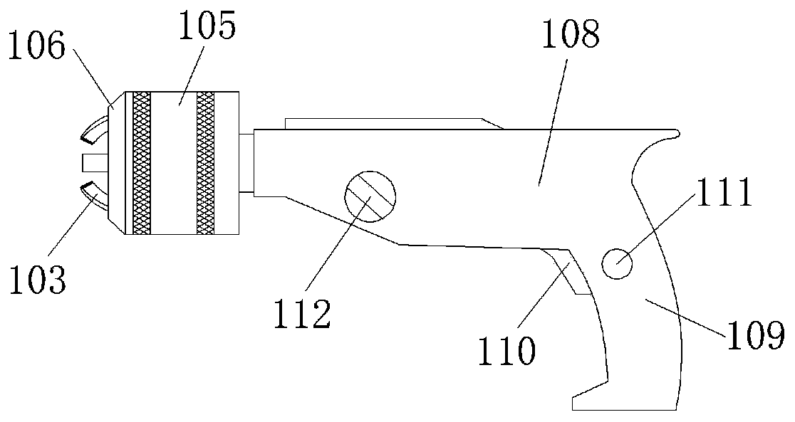
[0033] This embodiment provides a sampling machine, such as Figure 1-Figure 5 As shown, it includes a sampling head; the sampling head includes a threaded seat, a rotating seat 102 and a milling cutter 103; the rotating seat 102 is provided with a guide groove corresponding to the milling cutter 103; side; the end of the milling cutter 103 is provided with a blade 116, and the end is facing the axis of rotation; the end of the milling cutter 103 away from the end is the tail end, and the tail end is away from the axis of rotation; The axis of rotation has an included angle; the rotating seat 102 controls the rotation of the milling cutter 103 around the axis of rotation, and the threaded seat is provided with a tapered surface that matches the curved surface of the milling cutter 103; the tapered surface is provided with threads, and the milling cutter 103 faces the tapered One side of the surface is provided with a toothed section 115; the milling cutter 103 rotates along th...

Embodiment 2

[0047] This embodiment provides another structure of the threaded seat, such as Figure 9 As shown, it includes an inverted fixed seat 119, a round platform 117 and a fixed connecting rod 118; the side of the round platform 117 forms a tapered surface, and the thread is arranged on the side of the round platform 117 to form an external thread structure; the side of the milling cutter 103 facing the rotating shaft For the inner side, the tooth pattern segment 115 is arranged on the inner side of the milling cutter 103; the round table 117 and the milling cutter 103 are located on the same side of the rotating seat 102, and the round table 117 is located on the inner side of the milling cutter 103, and the milling cutter 103 rotates along the side of the round table 117; The rotation axis of the seat 102 is provided with a through hole that is rotatably matched with the fixed connecting rod 118; one end of the fixed connecting rod 118 is connected with the fixed seat 119, and the...


PUM


Abstract

The invention relates to a sampling machine. The sampling machine includes a sampling head; the sampling head includes a threaded seat, a rotating seat and a milling cutter; the milling cutter is arranged in the guiding groove of the rotating seat and located on one side of a rotating shaft; the end head of the milling cutter faces toward to the rotating shaft, and the tail end of the milling cutter is deviated from the rotating shaft; the rotating seat controls the milling cutter to rotate around the rotating shaft, and the threaded seat is provided with a conical surface matching the rotating surface of the milling cutter; the conical surface is provided with a thread, and the side, facing toward the conical surface, of the milling cutter is provided with a tooth pattern section; and the milling cutter rotates along the conical surface, and the thread meshes with the tooth pattern section to form a screw-pair structure of a leading screw. Improvement can be performed on the clamping jaw mechanisms of existing electric drills; the milling cutter can be driven to perform forward or reverse rotation around the rotating shaft through the rotation of the rotating seat, and the milling cutter can also perform telescoping movement during rotation, so that micro-damage sampling work can be accomplished; and the sampling machine has the advantages of being simple in structure, convenient in operation, good in stability, flat in sampled part and easy in welding and repairing after taking.

Description

technical field [0001] The invention belongs to the technical field of component surface sampling, and in particular relates to a sampling machine. Background technique [0002] At present, with the development of the modern energy industry, especially the development of large-scale coal-fired power generation units towards more efficient supercritical units, new materials are continuously applied to large-scale boiler equipment; due to these new heat-resistant steel materials (such as P92, P122 etc.) have not yet fully grasped the service characteristics, so it is necessary to conduct a full-life performance evaluation of the components. At the same time, with the country’s requirements for clean energy development, it is necessary to carry out feasibility studies and technical transformation of some in-service units to improve operating parameters, and these in-service units urgently need to carry out safety performance evaluation and life extension with the increase in se...

Claims


Application Information

Patent Timeline
Patent Type & Authority Applications(China)
IPC IPC(8): G01N1/04
CPCG01N1/04
Inventor 刘鸿国
Owner 国能神福(晋江)热电有限公司
Why Eureka
Try Eureka