Multi-scene visual robot simulation platform and method
A technology of simulation platform and simulation method, which is applied in the direction of instruments, simulators, measuring devices, etc., can solve the problems of image sensor field of view landmark point deterioration, image sensor noise, and positioning effect, etc., to achieve cost reduction and solve complexity , to achieve a simple effect
- Summary
- Abstract
- Description
- Claims
- Application Information
AI Technical Summary
Problems solved by technology
Method used
Image

Examples
Embodiment 1
[0041] Embodiment 1: as figure 2 , image 3 , Figure 4 and Figure 5 As shown, a multi-scenario visual robot simulation platform includes:
[0042] Data acquisition device: collect the actual information of the robot and transmit it to the AR image simulation device.
[0043] SLAM calculation module: it includes a calculation processing unit, an image processing unit and a communication unit.
[0044] AR image simulation device: Generate different scene information according to requirements.
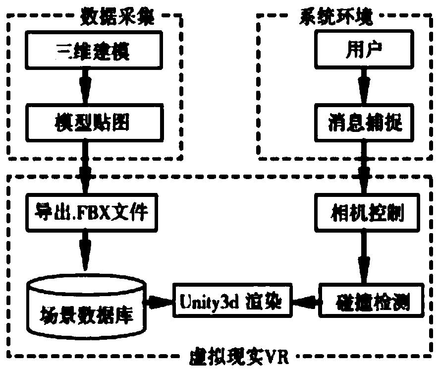
[0045] After the AR image simulation device acquires the data, it will construct the image scene. In terms of the design and construction of the image scene, the three-dimensional software 3Dmax is used to complete the modeling and texture. Drag and splice, you can actually open and close the door, you can switch the lights on the wall or move the furniture in the room, etc.
[0046] The construction plan is to use Unity3D. Unity3D is a multi-platform comprehensive game development...
Embodiment 2
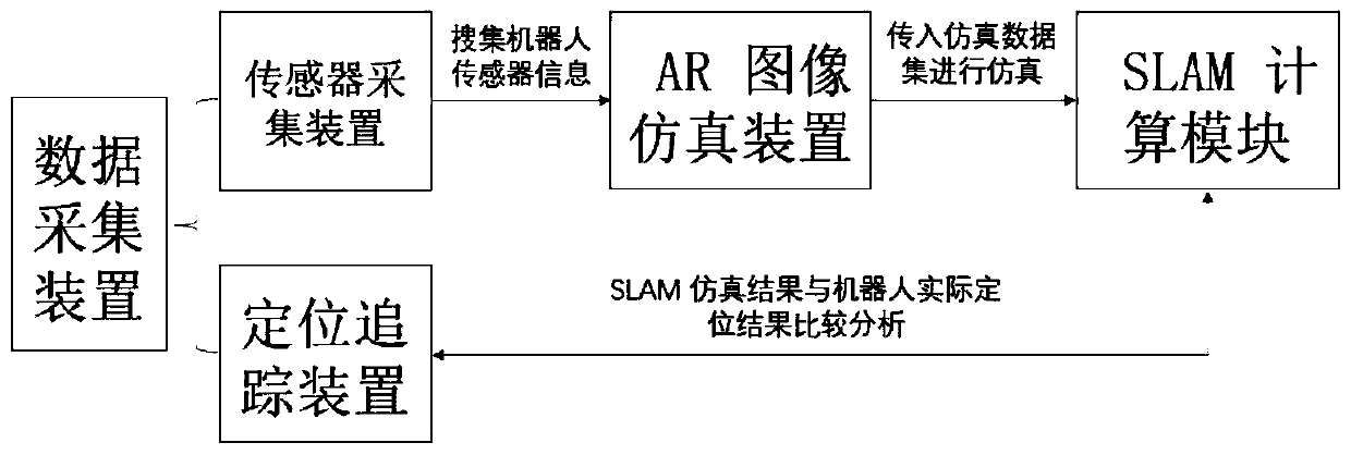
[0053] Embodiment 2: as figure 2 As shown, a multi-scenario visual robot simulation platform, its software architecture is:
[0054] Data acquisition includes two parts: sensor acquisition device and positioning tracking device.
[0055] The Slam calculation module receives the simulation information generated by the AR image simulation device.
[0056] Compare and optimize the overall test effect with the actual sweeping motion information.
[0057] Among them, the scene image information is transferred to the Slam calculation module by the AR image simulation device relative to the attitude change parameters of the self-propelled robot frame.
[0058] figure 2 A schematic flow chart of the method of the present invention is given in , wherein the robot simulation information is provided by the sensor acquisition device in the data acquisition device to provide robot sensor information and the AR image simulation device.
[0059] To obtain actual information from the da...
Embodiment 3
[0064] Embodiment 3: as figure 2 , image 3 , Figure 4 and Figure 5 Shown, a kind of multi-scenario visual robot simulation method contains following steps;
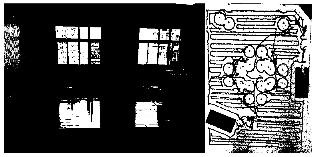
[0065] The sweeper robot will test the same family for different time periods and scenarios when conducting home tests.
[0066] image 3 The test was carried out in an environment with sufficient sunlight and clear viewing angles and scenes. It can be seen that the sweeper can be positioned very well in such an environment. After comparing with the actual positioning, we It is found that there is no large deviation, and the overall positioning effect vision is very close to the pose acquired by the positioning tracking device. In such a test scenario, the results obtained by SLAM are ideal.
[0067] Figure 4 The scene test was done at dusk when the sun is about to set. In such a scene, some places far away from the windows can no longer distinguish the details of the corners at this time. The actual test effe...
PUM
 Abstract
Description
Claims
Application Information
PatSnap Eureka turns technology decisions into work you can execute. Powered by our Innovation Knowledge Graph, it runs expert workflows across engineering, life sciences, materials and intellectual property. Get your review-ready output in minutes.


