
Drive circuit for soft-start contactor of frequency converter

A technology for driving circuits and contactors, applied in circuits, relays, electrical components, etc., can solve problems such as increasing the difficulty and cost of power supply design, electromagnetic interference, and affecting the normal operation of peripheral equipment, etc., to reduce the capacity of 24V power supply, 24V voltage The effect of the fluctuation reduction

Pending Publication Date: 2019-09-20
浙江阿尔法电气有限公司
View PDF0 Cites 0 Cited by
  • Summary
  • Abstract
  • Description
  • Claims
  • Application Information

AI Technical Summary

Problems solved by technology

However, because the current required for the contactor to pick up is very large, if there are N contactors, it needs N times the current of the single contactor's pick-up current to drive them to pick up at the same time, which will bring the following problems: 1. Driving the contactor The capacity of the driving power supply of the pull-in contactor needs to be large enough, which will greatly increase the design difficulty and cost of the power supply; 2. The large current and electromagnetic disturbance generated at the moment of contactor pull-in will cause great electromagnetic interference and affect peripheral equipment 3. The contactor drive element needs to withstand a large current instantaneously, and needs a high flow capacity

Method used


Image

  • Drive circuit for soft-start contactor of frequency converter
  • Drive circuit for soft-start contactor of frequency converter
  • Drive circuit for soft-start contactor of frequency converter

Examples


Embodiment 1

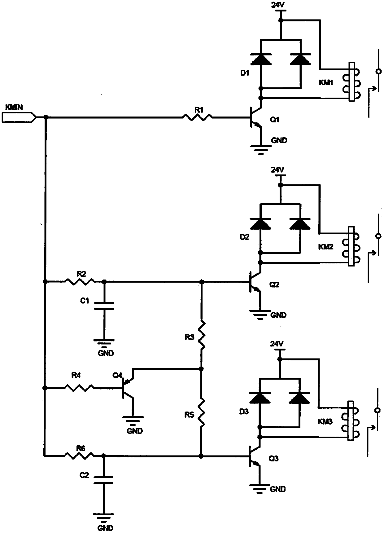
[0023] Such as figure 2 Shown is the first implementation example of the patent of the present invention.

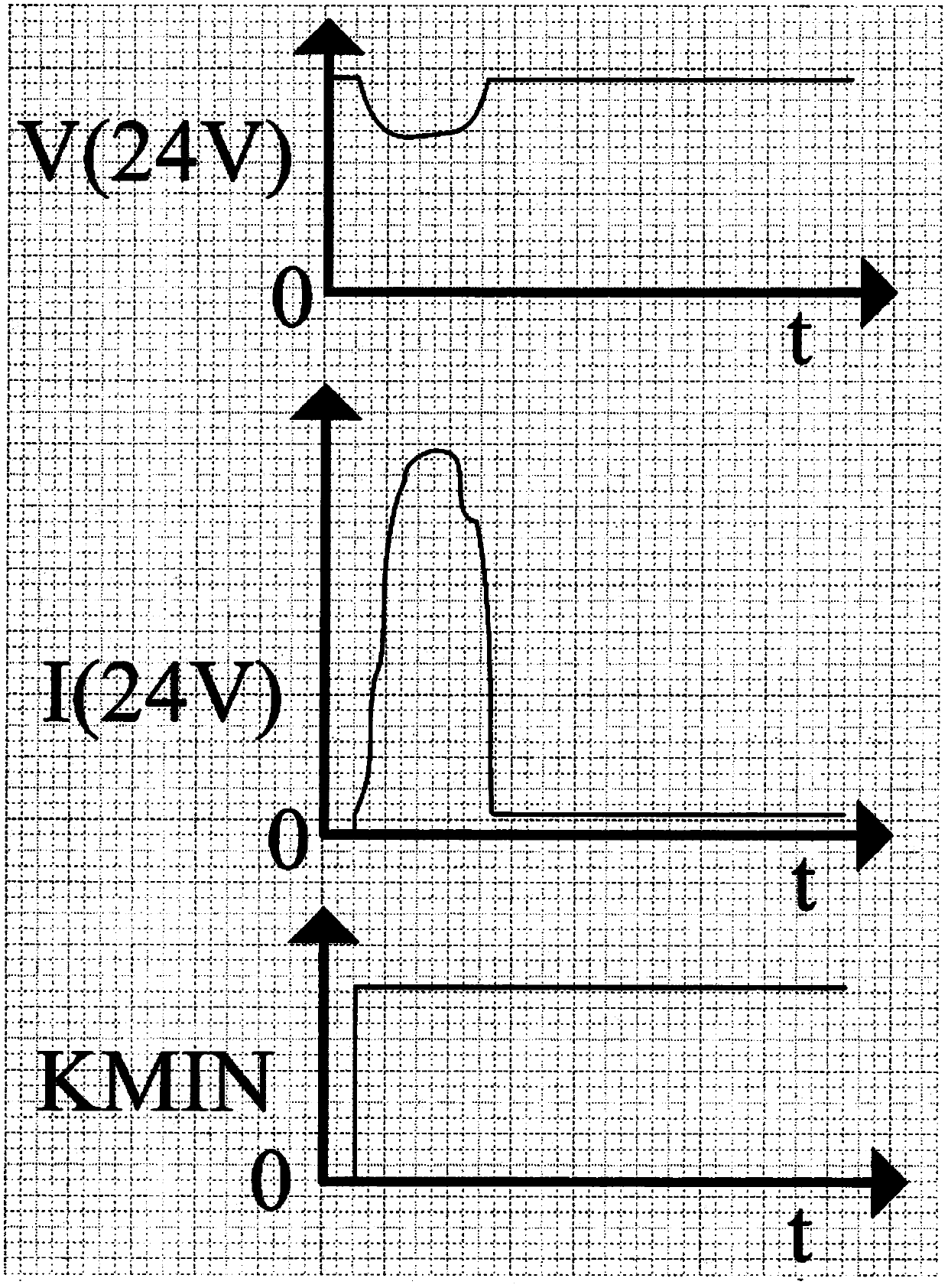
[0024] The contactor pick-up signal KMIN from the control system is connected to the base of the first triode Q1 through the first current limiting resistor R1, and the emitter of the first triode Q1 is connected to the contactor driving power ground GND, and the collector of Q1 The electrodes are connected to one end of the coil of the first contactor KM1, and the other end of the coil of the first contactor KM1 is connected to the positive terminal 24V of the contactor drive power supply. The first diode D1 is connected in parallel at the two ends of the coil of the first contactor KM1 to play the role of freewheeling. When the contactor pull-in signal KMIN signal is valid, that is, high level, Q1 will be turned on soon, the KM1 coil is energized, and KM1 pulls in. At the moment of KM1 pull-in current (mS level), the current absorbed by the KM1 coil from the 24V pow...


PUM


Abstract

The invention discloses a drive circuit for a soft-start contactor of a frequency converter, which realizes grouping and time-sharing driving of multiple contactors, enables the multiple contactors to close in a grouping and time-sharing manner and processes contactor closing signals from a control system. According to the invention, a first contactor driving unit directly receives a contactor closing signal of the control system and directly drives the first contactor to close without delay after the closing signal is valid; the contactor closing signal passes through a first delay unit and is then sent to a second contactor driving unit to drive the second contactor to close; the contactor closing signal passes through a second delay unit and is then sent to a third contactor driving unit to drive the third contactor to close; and a discharge unit discharges the delay units when the contactor closing signal is invalid, thereby effectively reducing the requirements for the capacity of a contactor driving power supply, also reducing the impact current of contactor closing and the level of electromagnetic interference caused by the impact current, and further reducing the requirements for the through-flow capacity of contactor driving elements at the same time.

Description

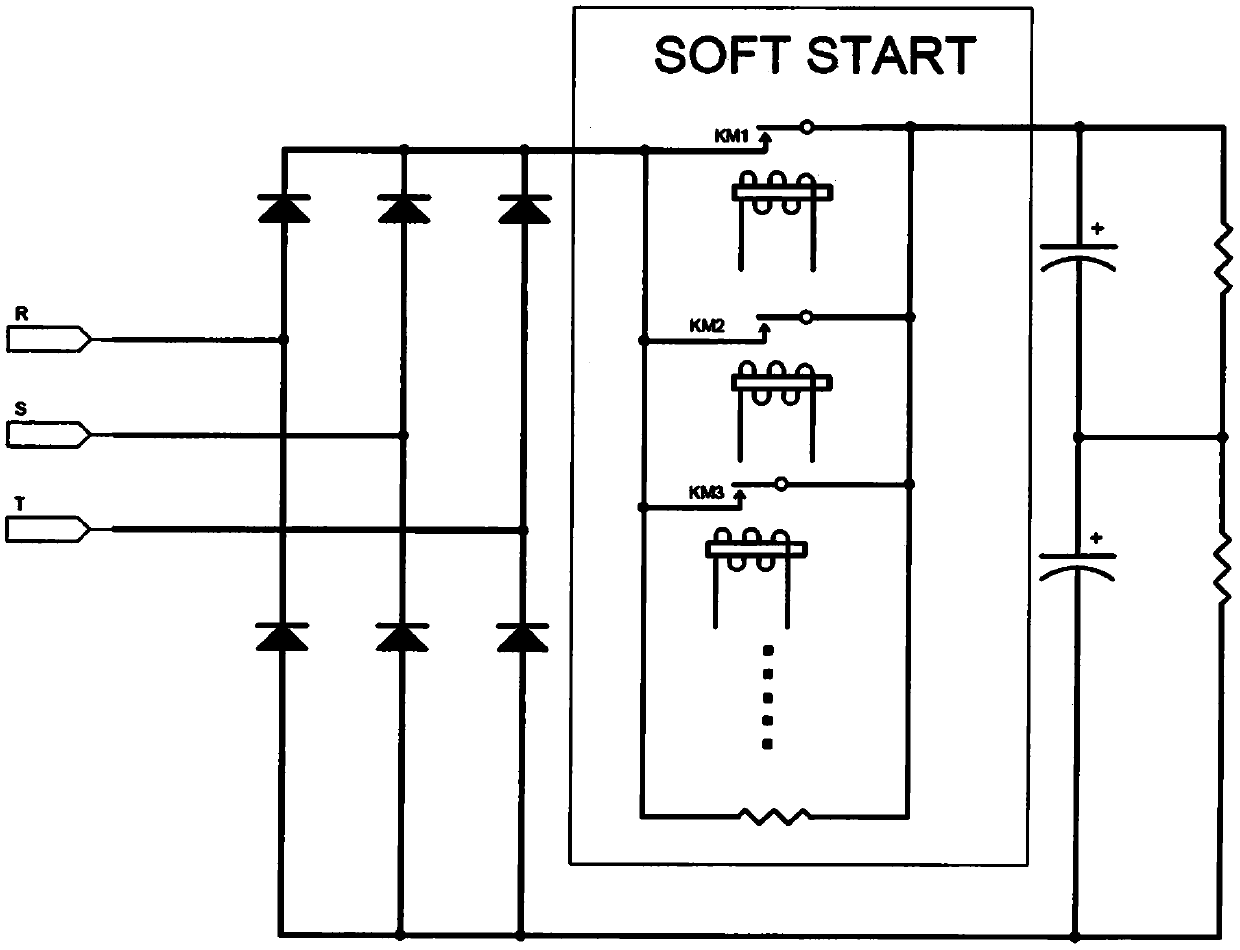
technical field [0001] The invention belongs to the field of electrical automation, and in particular relates to a drive circuit for a soft-start contactor of a frequency converter. Background technique [0002] In many occasions, such as high-power frequency converters and inverters, it is necessary to use multiple contactors in parallel. The current commonly used traditional circuit method is to simultaneously drive multiple contactors to pull in at the same time. However, because the current required for the contactor to pick up is very large, if there are N contactors, it needs N times the current of the single contactor's pick-up current to drive them to pick up at the same time, which will bring the following problems: 1. Driving the contactor The capacity of the driving power supply of the pull-in contactor needs to be large enough, which will greatly increase the design difficulty and cost of the power supply; 2. The large current and electromagnetic disturbance gene...

Claims


Application Information

Patent Timeline
IPC IPC(8): H01H47/00H01H47/32H02M1/36
CPCH01H47/002H01H47/32H02M1/36
Inventor 邬志国
Owner 浙江阿尔法电气有限公司
Learn More