Lithium battery laminating machine

A compound machine and lithium battery technology, which is applied in the direction of non-aqueous electrolyte battery, electrolyte battery manufacturing, sustainable manufacturing/processing, etc., can solve the problems of safety hazards, low production efficiency, etc., to improve production efficiency and reduce manual work time Effect

Pending Publication Date: 2019-09-20
东莞市联德企业管理有限公司
View PDF0 Cites 1 Cited by
  • Summary
  • Abstract
  • Description
  • Claims
  • Application Information

AI Technical Summary

Problems solved by technology

[0004] The purpose of the present invention is to provide a lithium battery composite machine, which aims to solve the technical problems that in the prior art, manual operation assistance needs to be added during the composite production process of lithium battery laminates, resulting in low production efficiency and potential safety hazards

Method used


Image

  • Lithium battery laminating machine
  • Lithium battery laminating machine
  • Lithium battery laminating machine

Examples


Embodiment 1

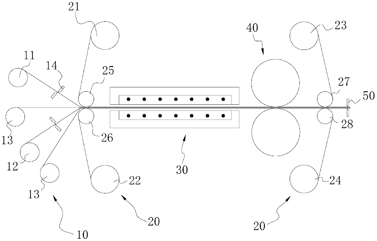
[0045] Such as Figure 1-7 As shown, this embodiment provides a lithium battery composite machine, which includes a feeding device 10 for inputting the diaphragm and the pole piece, and is used for stacking the pole piece and the diaphragm so that the pole piece and the diaphragm form a composite and The driving device 20 for transporting the composite, the heating device 30 for heating the composite to a preset high temperature, and the extrusion of the composite heated to a high temperature by the heating device 30 to make the pole piece and the separator at high temperature adhere A synthetic pressing device 40, and a cutting device 50 for cutting the formed composite to a preset length, the output end of the feeding device 10 is connected to the input end of the driving device 20, and the heating device 30 and the pressing device 40 are all arranged on the moving stroke of the composite body driven by the driving device 20, the heating device 30 and the pressing device 40 ...

Embodiment 2

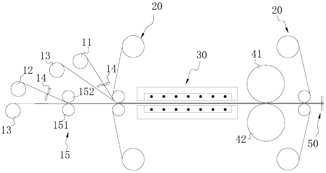
[0060] Such as figure 2 As shown, the feeding device 10 in this embodiment also includes a pair of roller drive mechanism 15, two groups of the third material roller 13, the first material roller 11, the pair of roller drive mechanism 15 and the second material roller. Rollers 12 are all arranged on one side of the first guide port, and the pair of roller driving mechanisms 15 are arranged between the third material roller 13 and the second material roller 12, and the pair of roller driving mechanisms 15 are used for To pre-compress the pole piece and the diaphragm conveyed by the second material roller 12 and the third material roller 13, so as to prevent the pole piece and the pole piece overlapped by the corresponding pole piece and the diaphragm from being guided through the first guide port The thickness of the complex composed of the diaphragm is too large to block the first guide port.

[0061] In this embodiment, the pair of roller driving mechanisms 15 includes a fo...

Embodiment 3

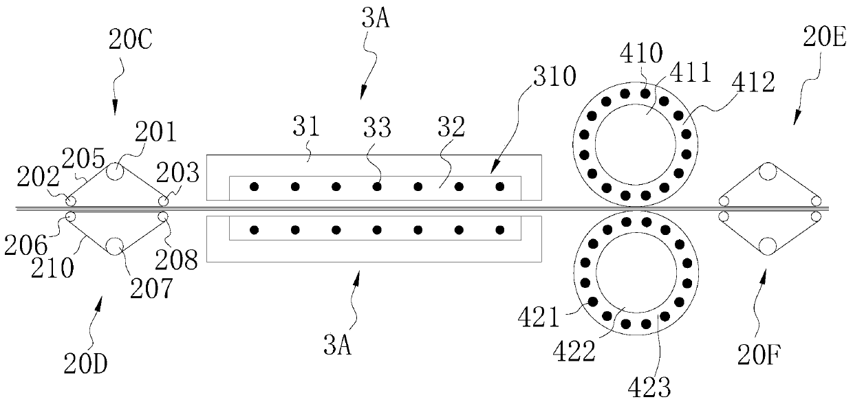
[0073] Such as image 3 As shown, the driving device 20 in this embodiment includes a fourth material roller 21, a fifth material roller 22, a sixth material roller 23, a seventh material roller 24, a first synchronous wheel assembly 20C, a second synchronous wheel assembly 20D, The third synchronous wheel assembly 20E, the fourth synchronous wheel assembly 20F, the first drive member (not marked in the drawings), the second drive member (not marked in the drawings) and the first drive motor (not marked in the figures), the first The fourth material roller 21 and the fifth material roller 22 are arranged symmetrically up and down, the sixth material roller 23 and the seventh material roller 24 are arranged symmetrically up and down, and the first synchronous wheel assembly 20C and the second synchronous wheel assembly 20C The synchronous wheel assembly 20D is arranged symmetrically up and down, the third synchronous wheel assembly 20E and the fourth synchronous wheel assembly ...


PUM


Abstract

The invention particularly relates to a lithium battery laminating machine, belonging to the technical field of lithium battery production equipment. The lithium battery laminating machine comprises a machine base, and further comprises a feeding device, a driving device, a heating device, a pressing device and a cutting device all arranged on the machine base, wherein the feeding device is used for inputting pole pieces and a diaphragm; the input end of the driving device is connected with the output end of the feeding device; the driving device is used for superposing the pole pieces and the diaphragm to allow the pole pieces and the diaphragm to form a composite body and for transporting the composite body; the heating device is used for heating the composite body to a predetermined high temperature; the pressing device is used for pressing the composite body so as to realize bonding and shaping of the high-temperature pole pieces and the high-temperature diaphragm; and the input end of the cutting device is connected with the output end of the driving device. The lithium battery laminating machine of the invention has the beneficial effects that the lithium battery laminating machine realizes automatic compounding of the pole pieces and the diaphragm, reduces manual operation and improves production efficiency.

Description

technical field [0001] The invention belongs to the technical field of lithium battery production equipment, and in particular relates to a lithium battery composite machine. Background technique [0002] As a new generation of chemical power sources, lithium-ion batteries are currently widely used in consumer electronics products due to their incomparable advantages over nickel-metal hydride, nickel-cadmium, and lead-acid batteries. They are also used as power batteries in various pure electric, in hybrid cars. At present, the production methods of lithium-ion batteries mainly include winding type and laminated type. From the perspective of lithium-ion battery performance and actual production: the advantage of winding type is that the manufacturing process is easy, and the advantage of stacked type is that the battery is of good quality in all aspects. , in order to combine the advantages of the two processes, people are currently focusing on the wound-type laminated batt...

Claims


Application Information

Patent Timeline
Patent Type & Authority Applications(China)
IPC IPC(8): H01M10/058
CPCH01M10/058Y02E60/10Y02P70/50
Inventor 温在东
Owner 东莞市联德企业管理有限公司
Why Eureka
Try Eureka